


Ensuring the reliability and performance of complex digital systems has two fundamental aspects: functional verification and digital design. Digital Design predominantly focuses on the architecture of the system that involves logic blocks, control flow units, and data flow units. However, design alone is not enough.
Functional verification plays a critical role in confirming if the design (digital system) behaves as intended in all expected conditions. It involves writing testbenches and running simulations that test the functionality of the design and catch bugs as early as possible. Without proper verification, even the most well-designed system can fail in real world use.
Coverage is a set of metrics/criteria that determines how thoroughly a design has been exercised during a simulation. It identifies and checks if all required input combinations have been exercised in the design.
There are several types of coverage used in modern verification flows, the first one being code coverage, which analyzes the actual executed code and its branches in the design. Functional coverage, on the other hand, is user-defined and tests the functionality of the design based on the specification and the test plan.
Coverage closure is a crucial step in the verification cycle. This step ensures that the design is robust and has been tested thoroughly. With an increase in scale and complexity of modern SoC/IP architectures, the processes required to achieve coverage closure become significantly difficult, time-consuming, and resource intensive.
Traditional verification involves a high degree of manual intervention, especially if the design is constantly evolving. This makes the verification cycle recursive, inefficient, and prone to human errors. Manual intervention in coverage closure remains a persistent challenge when dealing with complex subsystems and large SoCs.
Automation is not just a way to speed up the verification cycle; it gives us the bandwidth to focus on solving strategic design problems rather than repeating the same tasks over and over. This research is based on the same idea; it turns coverage closure from a tedious task to a focused, strategic part of the verification cycle.
This paper focuses on leveraging automation provided by the Cadence Incisive Metric Center (IMC) tool to minimize the need for manual effort in the coverage closure process. With the help of configurable commands in the Coverage Configuration File (CCF), we can exercise fine control in coverage analysis, reducing the chances of manual adjustments and making the flow dynamic.
Overview of Cadence IMC tool
IMC stands for Incisive Metrics Center, which is a coverage analysis tool designed by Cadence to help design and verification engineers evaluate the completeness of verification efforts. It works across the design and testbench during simulation to collect coverage data stored in a database. This database is later analyzed to identify the areas of design that have been tested and those which have not met the desired coverage goals.
IMC uses well defined metrics or commands for both code and functional coverage, which provide a detailed view of coverage results and identify any gaps to improve testing. The application includes the creation of a user-defined file called CCF, which includes these commands to control the type of coverage data that should be collected, excluded, or refined.
This paper offers several commands—such as “select_coverage”, “deselect_coverage”, “set_com”,”set_fsm_arc_scoring” and “set_fsm_reset_scoring”—which handle different genres of coverage aspects. The “select_coverage” and “deselect_coverage” commands automate the inclusion and exclusion activity by selecting specific sections of code as per the requirement, thus eliminating the manual exclusion process.
The “set_com” command provides a simple approach to avoid the manual efforts by automatically excluding coverage for constant variables. Meanwhile, the “set_fsm_arc_scoring” and “set_fsm_reset_scoring” commands focus more on enhancement of finite state machine (FSM) coverage by identifying state and reset transitions for the FSMs present in the design.
By using this precise and command-driven approach, the techniques discussed in this paper improve productivity and coverage accuracy. That plays a crucial role in today’s fast-paced complex chip development cycles.
Selecting/deselecting modules and covergroups for coverage analysis
The RTL design is a hierarchical structure which consists of various design units like modules, packages, instances, interfaces, and program blocks. It can be a mystifying exercise to exclude a specific code coverage section (block, expr, toggle, fsm) for the various design units in IMC tool.
The exercise to select/deselect any design units for code coverage can be implemented in a clean manner by using the commands mentioned below. These commands also provide support to select/deselect any specific covergroups (inside classes).
– deselect_coverage
The command can enable the code coverage type (block, expr, toggle, fsm) for the given design unit and can also enable covergroups which are present in the given class.
Syntax:

Figure 1 The above snapshot shows an example of select_coverage command. Source: eInfochips
This command is to be passed in CCF with the appropriate set of switches; <-metrics> defines the type of coverage metric like block, expr, toggle, fsm, and covergroup. According to the coverage metric, -module or -instance or -class is passed and then the list of module/instance/class is to be mentioned.
– deselect_coverage
The command can disable the code coverage type (block, expr, toggle, fsm) for the given design unit or can disable covergroups which are present in the given class.
Syntax:
deselect_coverage <-metrics> [-module | -instance | -class] <list_of_module/instance/class>

Figure 2 This snapshot highlights how deselect_coverage command works. Source: eInfochips
The combination of these two commands can be used to control/manage several types of code coverage metrics scoring throughout the design hierarchy, as shown in Figure 4, and functional coverage (covergroup) scoring throughout the testbench environment, as shown in Figure 7.
The design has hierarchical structure of modules, sub-modules, and instances (Figure 3). Here, no commands in CCF are provided and the code coverage scoring for all the design units is enabled, as shown in the figure below.
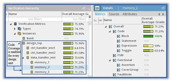
Figure 3 Code coverage scoring is shown without CCF Commands. Source: eInfochips
For example, let us assume code coverage (block, expr, toggle) scoring in ‘ctrl_handler’ module is not required and block coverage scoring in ‘memory_2’ instance is also not required; then in CCF, the deselect_coverage commands mentioned in Figure 4 will be used. To deselect all the code coverage metrics (block, expr, fsm, toggle), ‘-all’ option is used. Figure 4 also depicts the outcome of the commands used for disabling the assumed coverage.
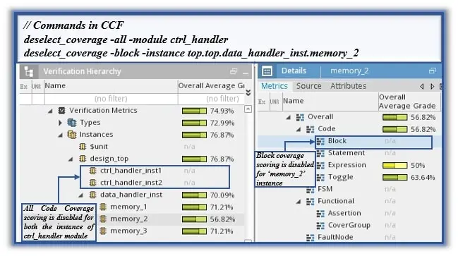
Figure 4 Code coverage scoring is shown with deselect_coverage CCF commands. Source: eInfochips
In another scenario, the code coverage scoring is required for the ‘design_top’ module, and the toggle coverage scoring is required for the ‘memory_3’ instance. Code coverage for the rest of the design units is not required. So, the whole design hierarchy will be de-selected and only the two design units in which the code coverage scoring is required are selected, as shown in Figure 5. The code coverage scoring generated as per the CCF commands is also shown in Figure 5.

Figure 5 Code coverage scoring is shown with deselect_coverage/select_coverage CCF commands. Source: eInfochips
The two covergroups (cg1, cg2) in class ‘tb_func_class ’ are scored when no commands in CCF are mentioned, as shown in Figure 6. In case functional coverage scoring of ‘cg2’ covergroup is not required, the CCF command mentioned in Figure 7 is used. For de-selecting any specific covergroup in a class, the ‘-cg_name’ <covergroup name> option is used
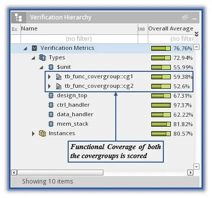
Figure 6 Functional verification is conducted without CCF command. Source: eInfochips
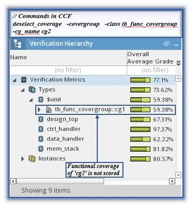
Figure 7 Functional verification is conducted with CCF command. Source: eInfochips
It’s important to note that both commands ‘select_coverage/deselect_coverage’ will have a cumulative effect on the coverage analysis. In <metrics> sub-option, ‘-all’ will include all the code coverage metrics (block, expr, toggle, fsm) but will not include -covergroup metric.
In the final analysis, by using the ‘select_coverage/deselect_coverage’ commands, code/functional coverage in the design hierarchy and from the testbench environment can be enabled and disabled from the CCF directly, which makes the coverage flow neat. If these commands are not used, to obtain a similar effect, manual exclusions from design hierarchy and testbench environment need to be performed in the IMC tool.
Smart exclusions of constants in a design
In many projects, there are some signals or codes of a design that are not exercised throughout the simulation. Such signals or codes of design create unnecessary gaps in the coverage database. To manually add the exclusion of such constant objects in all the modules/instances of design is an exhausting job.
Cadence IMC provides a command which smartly identifies the constant objects in the design and ignores them from the coverage database. It’s described below.
set_com
When the set_com command is enabled in the CCF, it identifies the coverage items such as an inactive block, the constant signals, and constant expressions, which remain unexercised throughout the simulation; it omits them from coverage analysis and marks them IGN in the output generated file.
Syntax:
set_com [-on|-off] [] [-log | -logreuse] [-nounconnect] [-module | -instance]
To enable the Constant Object Marking (COM) analysis, provide the [- on] option with the set_com command. When the COM analysis is done, the IMC generates an output file named “icc.com” which captures all the objects that are marked as constant.
By providing the [-log] option, it creates the icc.com file and ensures that the icc.com is updated each time for all the simulations. This icc.com file is created in the path “cov_work/scope/test/icc.com.” The COM analysis for specific module/instance is enabled by providing the [-module | -instance] option with the set_com command.

Figure 8 The above image depicts the design hierarchy. Source: eInfochips

Figure 9 The COM analysis command is shown as mentioned in CCF. Source: eInfochips
Consider that the “chip_da” variable of the design remains constant throughout the simulation. By enabling the set_com command as shown in Figure 9, the variable chip_da will be ignored from the coverage database, which is shown in Figure 10 and Figure 11.
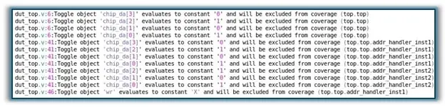
Figure 10 The icc.com output file is shown in the coverage database. Source: eInfochips
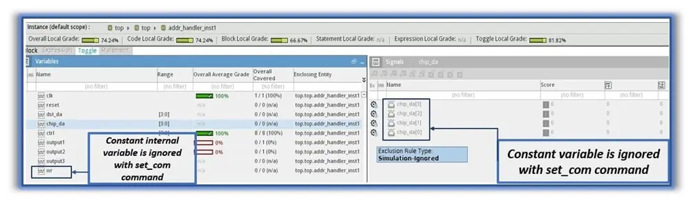
Figure 11 Constant variable chip_da is ignored with set_com command enabled. Source: eInfochips
COM analysis
In the CCF, the set_com command is enabled for the addr_handler_instance1 instance.
- Here, as the set_com command is enabled, the “chip_da” signal, which remains constant throughout the simulation, will be ignored from coverage analysis for the defined instances. As shown in Figure 10, in every submodule where the chip_da signal is passed, it gets ignored as the chip_da signal is the port signal, and the COM analysis is done based on the connectivity (top-down/bottom-up).
- Along with the port signals, the internal signals which remain constant, are also ignored from the coverage database. In Figure 10, the “wr” signal is an internal signal and it’s ignored from the coverage database (also reflected in Figure 11).
- The signal chip_da is constant for this simulation (which is IGN) while if chip_da is variable for some other simulation (which is covered/uncovered) and these two simulations are merged. Then the signal chip_da will be considered as a variable (covered/uncovered) and not an ignored constant.
It’s worth noting that when the set_com command is enabled for a module/instance, and if the signal is port signal and is marked as IGN, then the port signals of other sub-modules, which are directly connected to this signal, are also IGN irrespective of the command enabled for that module/instance.
Finally, to avoid the unnecessary coverage that is captured for constant objects and to save time in adding exclusion for such constant objects, the set_com command is extremely useful.
Detailed analysis of FSM coverage
A coverage-driven verification approach gives assurance that the design is exercised thoroughly. For the FSM-based design, there are several types of coverage analysis available. FSM state and transition coverage analysis are the two ways that help to perform the coverage-driven verification of FSM designs, but it’s not a complete verification of FSM designs.
FSM arc coverage provides a comprehensive analysis to ensure that the design is exercised thoroughly. To do that, Cadence IMC provides some CCF commands, which are described below.
set_fsm_arc_scoring
The FSM arc coverage is disabled by default in ICC. It can be enabled by using the set_fsm_arc_scoring command in the CCF. The set_fsm_arc_scoring enables the FSM arcs, which are nothing but all the possible input conditions for which transitions take place between the two FSM states.
Syntax:
To enable the FSM arc coverage, provide the [-on] option in the set_fsm_arc_scoring. The FSM arc coverage can be encompassed for all the FSMs defined in a module by providing the [-module <module_name>] option.
If the FSM arc coverage needs to be captured for specific FSM in the module, it can be achieved by providing the tag name to FSM using the set_fsm_attribute command in the CCF. By providing tag name option with set_fsm_arc_scoring, FSM arc coverage can be captured for the FSM in design.
set_fsm_reset_scoring
A state is considered a reset state if the transition to that state is not dependent on the current state of the FSM; for example, in the code shown below.
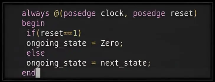
Figure 12 Here is an example of a reset state. Source: eInfochips
State “Zero” is a reset state because the transition to this state is independent of the current state (ongoing_state). By default, the FSM reset state and transition coverage are disabled in ICC, as shown in Figure 13. They can be enabled using the set_fsm_reset_scoring command in the CCF. This command enables scoring for all the FSM reset states and transitions leading to reset states that are defined within the design module.
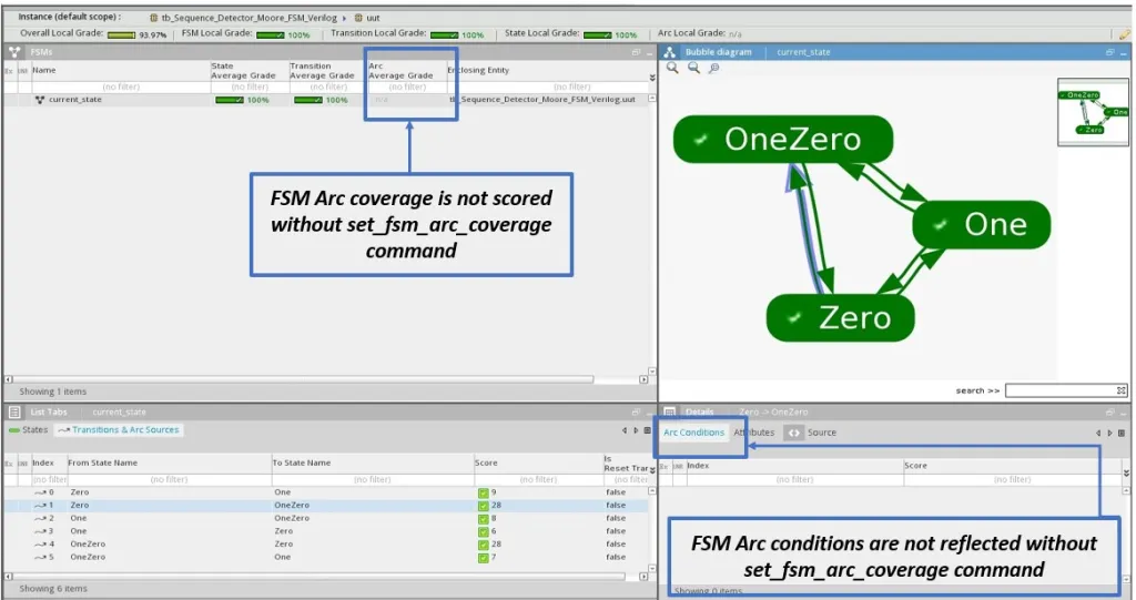
Figure 13 FSM coverage is shown without set_fsm_arc_scoring command. Source: eInfochips
Syntax:
set_fsm_reset_scoring
In the design, there are two FSMs defined—fsm_design_one and fsm_design_two—and we are enabling the FSM arc and reset state and transition coverage for fsm_design_two only. If the set_fsm_arc_scoring and set_fsm_reset_scoring commands are not provided in the CCF, the FSM arc, FSM reset state and transition coverage are not enabled, as shown in Figure 13.
If the set_fsm_arc_scoring and set_fsm_reset_scoring commands are provided in the CCF, as shown in Figure 14, then the FSM arc, the FSM reset state, and the transition coverage are enabled as shown in Figure 15.
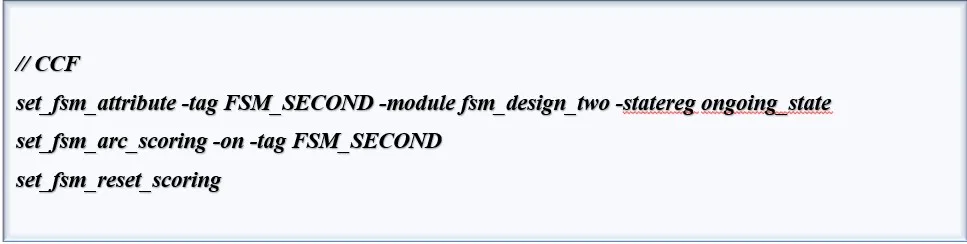
Figure 14 The set_fsm_arc_scoring and set_fsm_reset_scoring commands are provided in CCF. Source: eInfochips
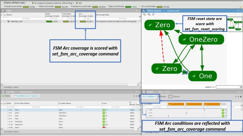
Figure 15 FSM coverage is shown with set_fsm_arc_scoring and set_fsm_reset_scoring commands. Source: eInfochips
In case the design consists of FSM(s), and to ensure that the FSM design is exercised thoroughly, and it’s verified based on a coverage-driven approach, one should enable the set_fsm_arc_scoring and set_fsm_reset_scoring commands in the CCF files.
Efficient coverage closure
Efficient coverage closure is essential for ensuring thorough verification of complex SoC/IP designs. This paper builds on prior work by introducing Cadence IMC commands that automate key aspects of coverage management, significantly reducing manual effort.
The use of select_coverage and deselect_coverage enables precise control over module and covergroup coverage, while set_com intelligently excludes constant objects, improving the coverage accuracy. Furthermore, set_fsm_arc_scoring and set_fsm_reset_scoring enhance the FSM verification, ensuring that all state transitions and reset conditions are thoroughly exercised.
By adopting these automation-driven techniques, verification teams can streamline the coverage closure process, enhance efficiency, and maintain high verification quality, improving productivity in modern SoC/IP development.
Rohan Zala, a senior verification engineer at eInfochips, has expertise in in IP/SoC verification for sensor-based chips, sub-system verification for fabric-based design, and NoC systems.
Khushbu Nakum, a senior verification engineer at eInfochips, has expertise in IP/SoC verification for sensor-based chips and sub-system verification for NoC design.
Jaini Patel, a senior verification engineer at eInfochips, has expertise in IP/SoC verification for sensor-based chips and SoC verification for signal processing design.
Dhruvesh Bhingradia, a senior verification engineer at eInfochips, has expertise in IP/SoC verification for sensor-based chips, sub-system verification for fabric-based design, and NoC systems.