
An Overview
A traction inverter is the heart of an electric vehicle system. The inverter has a particularly important role in the adoption of EVs globally. The traction motor provides acceleration and torque by converting DC power from the generator or batteries to AC power to supply power to traction drive motors such as externally excited synchronous motors (EESM), permanent magnetic machines (PMSM), switched reluctance motors (SRM), and induction motors (IM).
Hereunder is a high-level block diagram of a traction inverter:
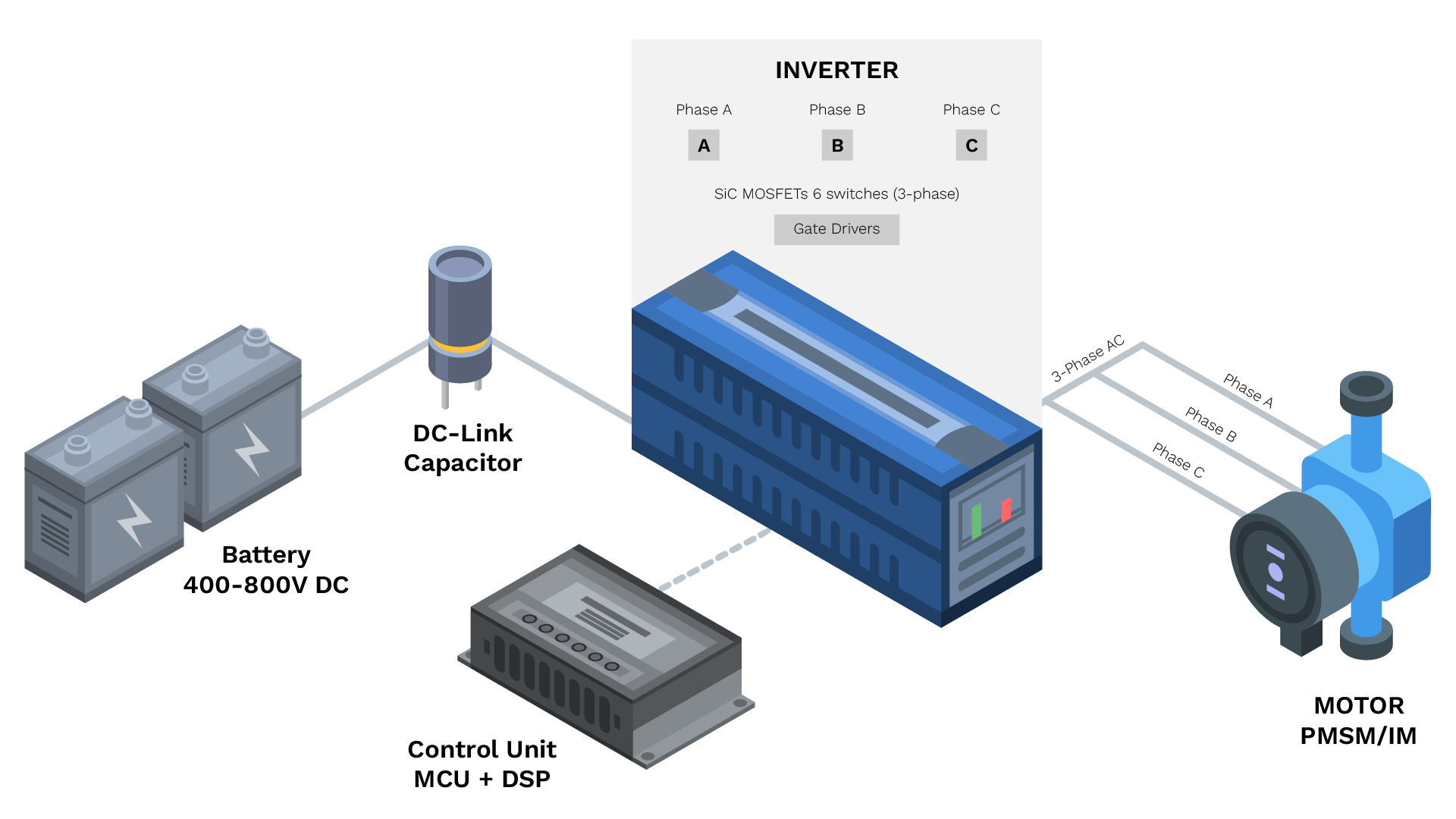
A High-level Block Diagram of a Traction Inverter
Architecture
The traction inverter has a complex architecture, and it also varies with the type of vehicles. Battery electric vehicles (BEVs) and Plug-in hybrid electric vehicles (PHEVs) have a 3-phase voltage topology, it has power levels in the range of 100 kW to 500kW. However the two-level inverter is the most common power converter used in electrified vehicles with a power range of tens of kilowatts up to hundreds of kilowatts. The figure below illustrates an example of a three-level T-type inverter:
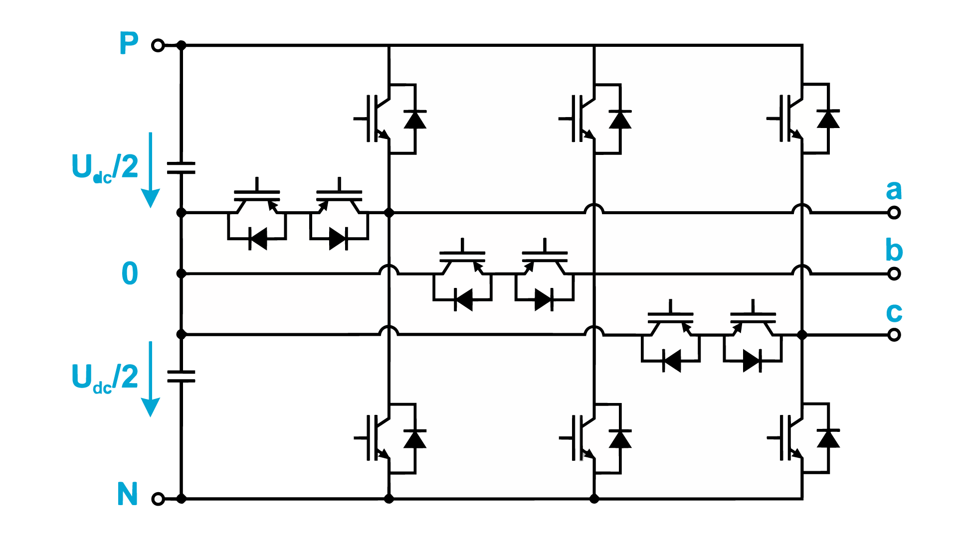
Source – TI Traction Inverter Whitepaper 3-level T-type inverter
Key Technology Enablers and Power Density for an EV Traction Inverter
Before we dive deep into the design considerations for a traction inverter, it is important to understand the technologies involved in a traction inverter.
A traction inverter requires:
- Isolation technology
- Technology implemented on the high-voltage domain, and
- Low-voltage domain
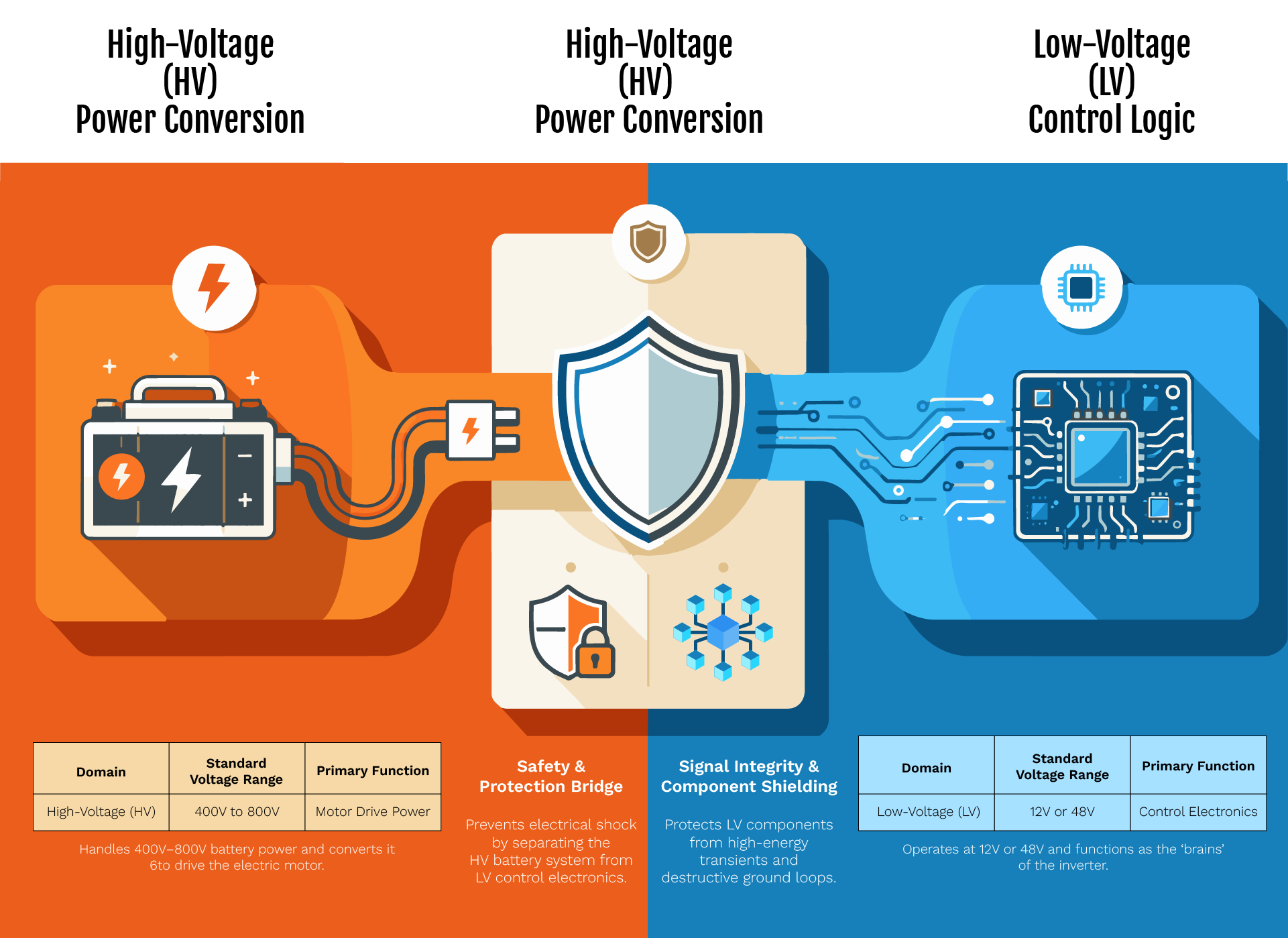
In a traction inverter, isolation technology bridges the gap between the high-voltage (HV) battery system and the sensitive low-voltage (LV) control electronics, using galvanic isolation and signal isolation for safe communication between control electronics and high-voltage stages. It ensures safety by preventing electrical shock and protects low-voltage components from high-energy transients and ground loops.
The high voltage traction inverter technology handles the power from the vehicle’s battery (typically ranging from 400V to 800V, with the industry shifting toward 800V architectures for faster charging and higher power density) and converts it to drive the motor. Whereas the low-voltage technology operates at standard vehicle voltages (e.g., 12V or 48V) and houses the “brains” of the inverter.
In software defined vehicles, the traction inverter increasingly exchanges data with the vehicle network, vehicle control unit, and battery management system, while tighter integration with other systems and DC/DC converters can reduce system weight and parasitic losses.
Key Technology Enablers for an EV Traction Inverter
Key Design Considerations and Thermal Management of an EV Traction Inverter
The traction inverter is a complex device. There are various factors that can affect its performance. Engineers must consider the followings items in order to balance power efficiency with thermal management and overall system performance:
Voltage Isolation
In terms of traction inverter voltage, isolation means separating high voltage domains from the low voltage domains, especially in automotive applications. Various electronic components operate at a few volts, but many other components operate at an exceedingly high voltage. Therefore, it is important to have strong voltage isolation. A high voltage domain refers to 400-800V from battery and power switches, while low voltage for example, is 3.3-5V MCUs and sensors.
It is an essential separation because it protects against ground shift, transients, and shocks during fast switching. If an engineer fails to comply with this, there may be short circuits, and risks of system failure and other safety hazards.
Thermal Management
Thermal management in an EV traction inverter means dissipating heat from power modules, semiconductors, capacitors, and other electronic components with robust thermal management, while advanced thermal interface materials minimize thermal resistance and support thermal stability. These components in an inverter run continuously at high voltage, around 30kW to up to 200kW at peak loads. This generates significant heat in the system, and it is important to manage it for an effective operation.
There are 2 main cooling methods which an engineer can implement to prevent overheating, air cooling and direct liquid cooling.
Direct liquid cooling is used for high-density systems with >50 kW/L. As it efficiently removes heat from highly packed SiC/IGBTs during continuous 30 kW operations and 200 kW peak operations, and these high power inverters must still fit compact designs with hundreds of kilowatts in small, lightweight packages. Air cooling is only suitable for low-density systems with < 20kW/L, but it overheats at peaks. It is only suitable for mild hybrid systems.
Modern premium EVs increasingly use silicon carbide and silicon carbide sic devices because they deliver higher efficiency, improved power density, and support more compact designs. SiC can improve traction inverter efficiency by about 30%, support switching frequencies above 100 kHz, and reduce switching losses by up to 50% versus insulated gate bipolar transistors.
There are various design elements which engineers can consider:
- Thermal interface materials (TIMs) with conductivity >3 W/mK
- A cold plate design optimized for uniform temperature distribution (±5°C)
- Junction temperature monitoring and active derating to prevent thermal runaway
- Maximum junction temperatures: Si IGBTs (150-175°C), SiC MOSFETs (175-200°C)
EMI Interference
The traction inverter has to quickly convert DC power from battery to AC power for the motor. This fast switching of power semiconductors like SiC MOSFETs improves efficiency but also increases electromagnetic interference.
There are various EMI mitigation techniques that can be implemented. Some of these are PCB layout optimization, shielding, switching control, grounding practices, and topology choices. Busbar and dc link capacitor layout also affect electromagnetic emissions, while low-inductance film capacitors improve reliability under high-frequency switching.
Motor Control
In an EV traction inverter, motor control design involves implementing real-time motor control algorithms for inverter control. These algorithms must run continuously to deliver precise torque and speed (0-20,000 RPM). This can be done by using a feedback mechanism from high-resolution current sensors to monitor motor current, meet torque demand, and execute torque commands precisely for field-oriented control (FOC) on PMSMs (Permanent Magnet Synchronous Motors), which enables a smoother driving experience with responsive torque delivery. Engineers can prioritize low-latency loops (< 1 µs), computational efficiency, and ASIL-D safety to avoid torque ripple.
Adaptive modulation strategies can improve efficiency across different operating ranges, including regenerative braking.
Functional Safety
Traction inverters are designed to meet functional safety requirements such as ISO 26262. It ensures that the system detects faults. The traction inverter is a safety critical device and is rated at ASIL D. Here the primary safety goals include:
- Avoidance of unintended torque which means preventing motors from producing torque without the driver’s command
- Avoidance of reverse torque means a vehicle would only move as per the gear selection
- Active discharge means reducing high-voltage level to less than 60V after a crash or maintenance
There are various safety mechanisms which engineers can look into:
- Hardware: Redundant microcontrollers with lockstep cores, watchdog timers, memory protection units, CRC-protected communication, diverse sensor redundancy.
- Software: MISRA C compliance, software-based fault detection (current limit monitoring, voltage range checks, temperature monitoring), safe state transitions, comprehensive diagnostics with fault memory.
- Diagnostic Coverage: Target >99% for ASIL-D. Includes overcurrent protection (< 10 μs), overvoltage/undervoltage detection, overtemperature shutdown, short-circuit detection, insulation monitoring, and phase loss detection.
Below is the image representation of functional safety architecture for an EV traction inverter:
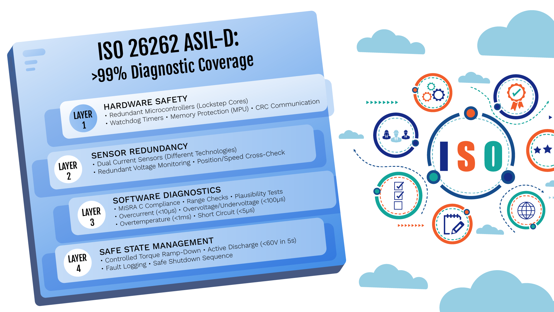
Functional Safety Architecture for an EV Traction Inverter
Environmental Conditions
A traction inverter must be a rugged device. It must go through rigorous vibration, thermal, EMI testing for an efficient performance as per the ISO 16750 standards.
Engineers should target IP67 sealing, with temperature operating rage of-40°C to 125°C. It should also operate under 10G shock vibration endurance.
Engineers must look at the lifetime target of 15-year operational life or 200,000-300,000 km (depending on vehicle class).
Let us look at the summary of the given design considerations in the image below:
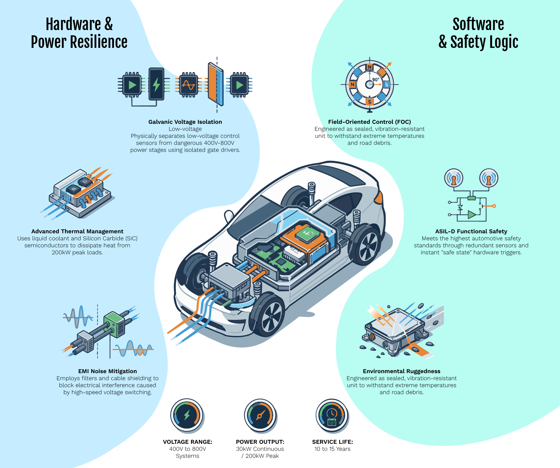
Key Design Considerations for an EV Traction Inverter
Components Cost Breakdown and Loss Analysis
Let us also look at the breakdown of the component costs which are involved in a traction inverter. This is based on a 100 kW inverter at high volume (>100k units/year):
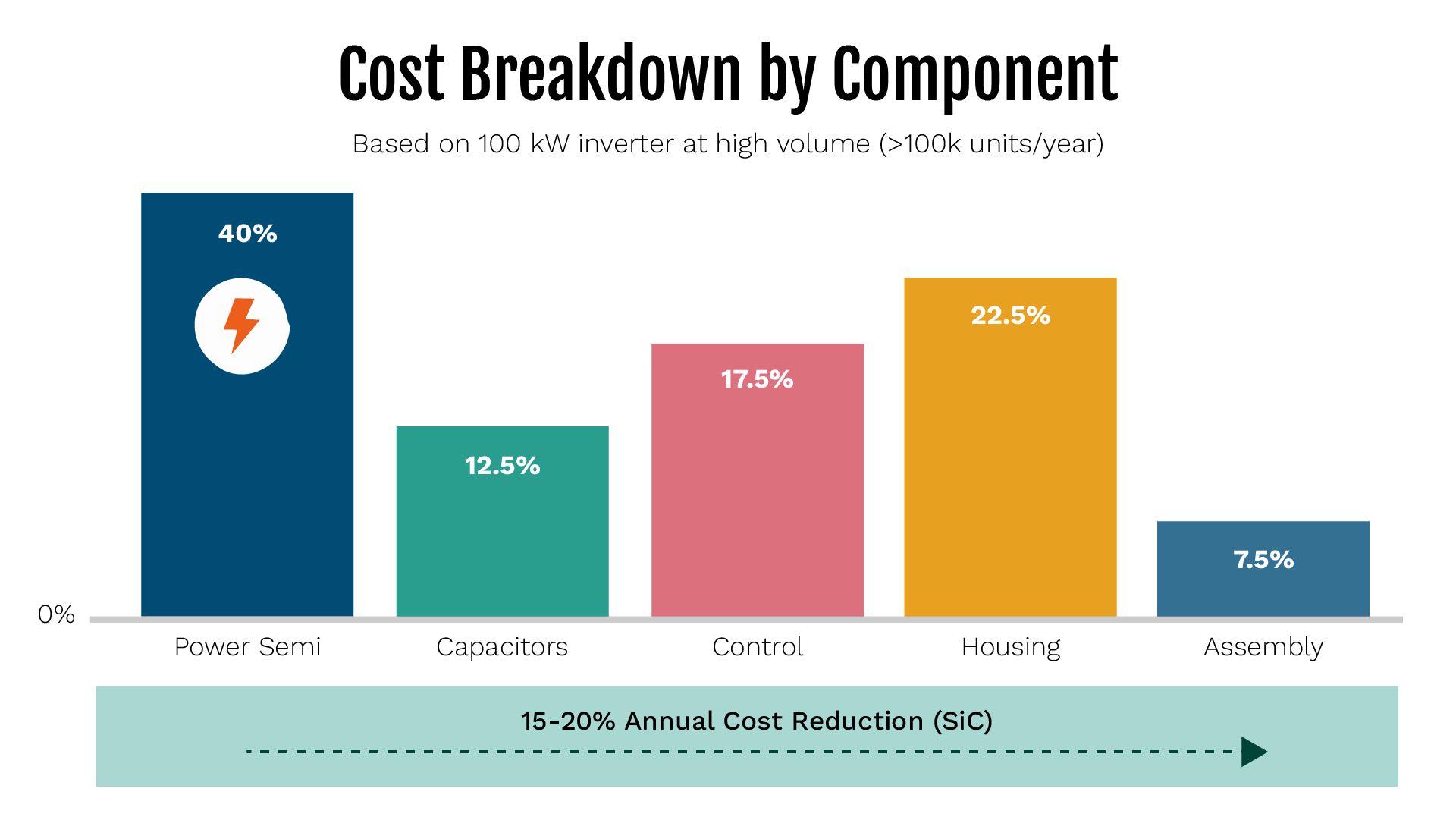
Also look at the cost drivers for each component in the table below:
| Component | % range of Total | Cost Drivers |
| Power Semiconductors | 35-45% | SiC premium (1.5-2x vs Si) |
| DC-Link Capacitors | 10-15% | Film capacitor cost, volume |
| Gate Drivers and Control | 15-20% | Isolation, MCU capability |
| Housing and Cooling | 20-25% | Aluminum casting, machining |
| Assembly and Testing | 10-15% | Manual processes, test time |
It is also important to look at the efficiency analysis and the loss breakdown for each component. Conduction in semiconductors contributes to major losses in the system. Let us understand this through the following diagram:
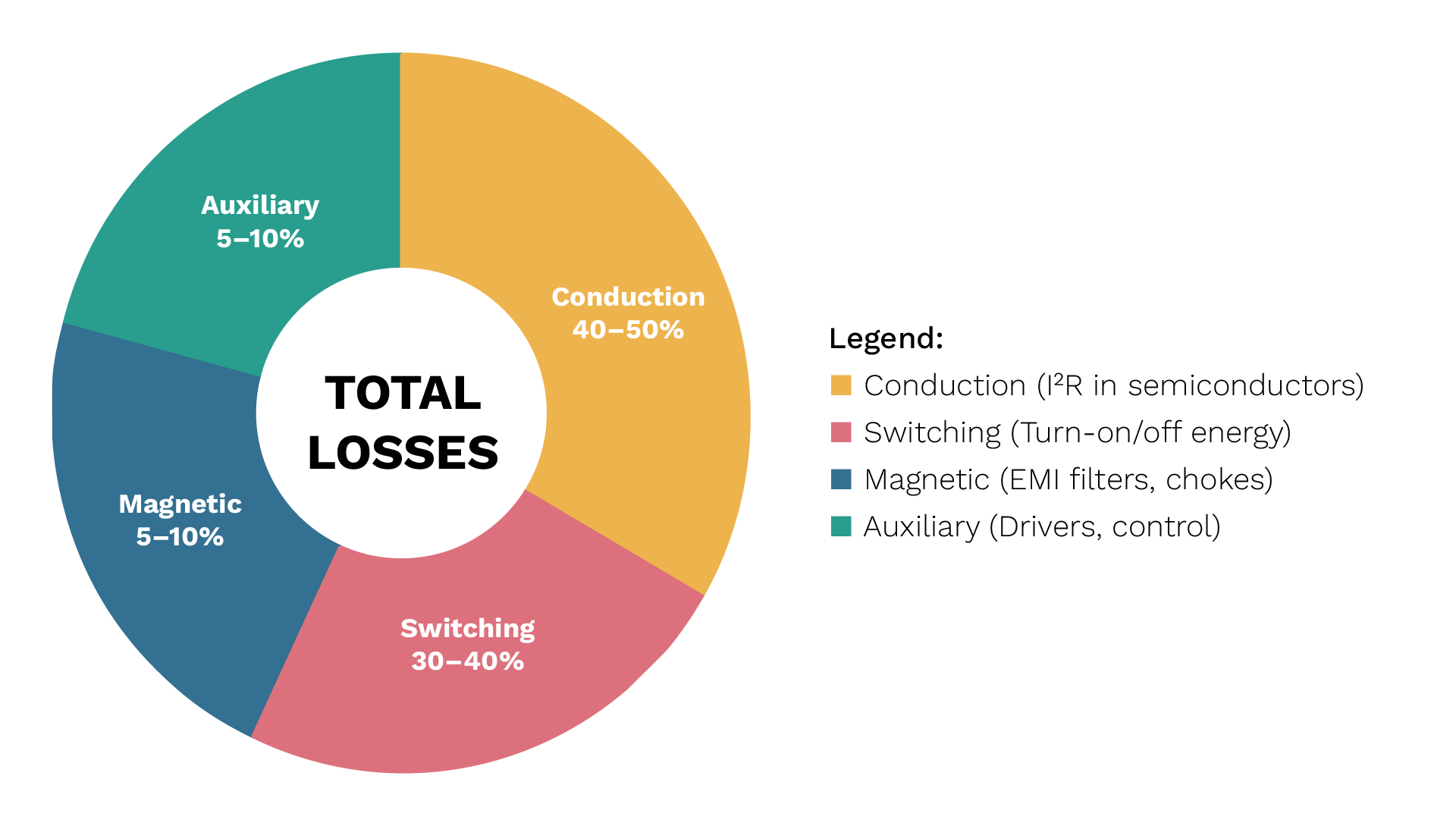
We will also take a look at some of the mitigation techniques in this table:
| Loss Type | Percentage | Primary Factors | Mitigation |
| Conduction | 40-50% | On-state resistance, I²R | SiC devices, parallel devices |
| Switching | 30-40% | Turn-on/off energy, frequency | SiC, soft switching |
| Magnetic | 5-10% | EMI filters, core/copper | Low-loss materials |
| Auxiliary | 5-10% | Gate drivers, control, cooling | Efficient drivers |
Conclusion
As the automotive industry is progressing rapidly, it is important to design a fail-proof, and ruggedized traction inverter. For engineers, it is essential to keep various aspects in mind while designing a traction inverter.
eInfochips works across the full stack of power electronics and embedded control for traction inverters. We work closely with OEMs and Tier-1 suppliers on custom inverter designs, motor control tuning, and thermal management.
Our team can deliver complete inverter solutions. We also validate ev traction inverters with high-performance test setups that use multichannel mixed signal oscilloscopes and high-power bidirectional power supplies. Application notes support this approach, including traction inverter efficiency testing that compares input and output power ratios. We have strong capabilities in hardware design, embedded software, power electronics, and automotive safety standards such as ISO 26262. These solutions are built to meet automotive performance, efficiency, and long-term reliability requirements.
Frequently Asked Questions
1. Is SiC always better than IGBT for EV traction inverters, or are there cases where IGBTs still make sense?
SiC isn’t universally better; it’s a trade-off. IGBTs remain cost-competitive for lower-power applications (mild hybrids, budget EVs) where switching losses matter less and price sensitivity is high. SiC pulls ahead in high-power, high-efficiency applications (800V platforms, premium/performance EVs) where its 2-3% efficiency gain and reduced cooling needs justify the 1.5-2x cost premium. As SiC costs decline 15-20% annually, this threshold keeps shifting in its favour. For most new 800V platform designs launching after 2026, SiC is becoming the default choice rather than the exception.
2. How does inverter efficiency actually translate into real-world driving range?
A 2-3% efficiency improvement (typical SiC vs Si gain) doesn’t sound like much, but it compounds. Over a full drive cycle, this typically adds 5-8% to vehicle range. It’s meaningful when a 300-mile EV gains 15-24 extra miles. The impact is largest at highway speeds and during regenerative braking, where the inverter operates continuously near its efficiency sweet spot. It’s also compounding: better efficiency means smaller batteries can achieve the same range, reducing weight and further improving efficiency. A virtuous cycle that’s driving much of the industry’s push toward SiC adoption.
3. With ASIL-D safety requirements, how much more expensive is a traction inverter compared to a non-safety-critical power converter?
Safety-critical design typically adds 15-25% to the overall system cost, primarily due to redundant sensors, dual-microcontroller architectures, and the extensive validation testing required for >99% diagnostic coverage. However, this isn’t optional overhead. ISO 26262 ASIL-D compliance is mandatory for production vehicles, not a premium feature. The real cost driver is validation time, not hardware: fault injection testing and HIL simulation across millions of scenarios can add 6-12 months to development. Manufacturers increasingly absorb this cost through platform reuse across multiple vehicle programs rather than treating it as a per-project expense.