
Simulation shows what is possible. Formal proves what is guaranteed.
An Overview of Hardware Design
In complex ASIC verification, when multiple control-heavy digital logic blocks have to work together, simulation and testing alone cannot guarantee that everything works perfectly because they are limited by time and resources. That is where formal verification comes in: a mathematical analysis method used to prove design correctness against expected behavior, making it a vital part of sign-off for ASIC designers, verification engineers, and other semiconductor teams working on complex controllers and SoCs.
In this article, we discuss how we used formal methods, especially formal property verification (FPV) and connectivity verification in JasperGold, to make sure that a central digital controller was working correctly with more than 30 configurable, independently operating modules. We also discuss concrete solutions, not theories. These include CSV-based signal mapping, sequential connectivity and delay modeling, scalable parameterized assertions, assumptions to manage proof complexity, sanity checks, and behavioral demonstrations that the FSM will not go rogue in edge cases when checked against a clear specification—while keeping in mind that any proof is only as good as the specification it is based on.
Connectivity Verification: Structure Before Behavior
When the design has dozens of RTL modules that are copies of each other, even one signal that is not connected correctly can cause problems with functionality. We checked signal connections thoroughly at the implementation level in the register transfer level code before making any behavioral assumptions about the hardware design.
[1] The JasperGold Connectivity App was used to perform this.
Here is a picture of how the signal travels from the source to the destination through layered modules:
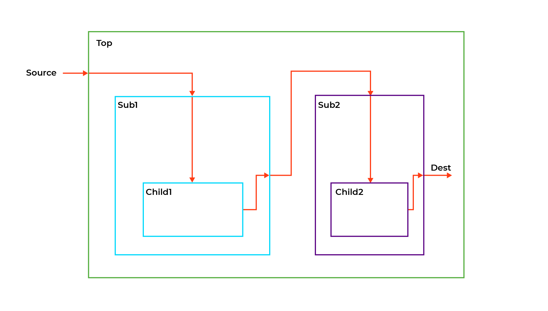
We made a structured Connectivity Map in the CSV format that shows all the pairings of signals going from one source to another.
As an example:
CONNECTION, simple_conn, source, sub2.child2, dest
The JasperGold tool read this CSV and made assumptions like this one:
assert property ((posedge clk) sub2.child2.dest == source);
Before the simulation commenced, this method helped us detect design flaws early, including silent issues like swapped control lines, missing assignments, or instance paths that were no longer valid.
Sequential Connectivity and Conditional Connectivity: Capturing Delayed Paths with PIPE Constructs
Not all links in digital designs are just combinational. A signal from the top level may have to traverse through one or more flops (registers) before it gets to its destination. From a functional point of view, the destination is still “connected” to the source, but there is a delay over a specific cycle depth. In formal connectivity tests, this kind of a delayed path needs extra care. That is where the PIPE component in JasperGold’s Connectivity App is handy.
This is the structural path:
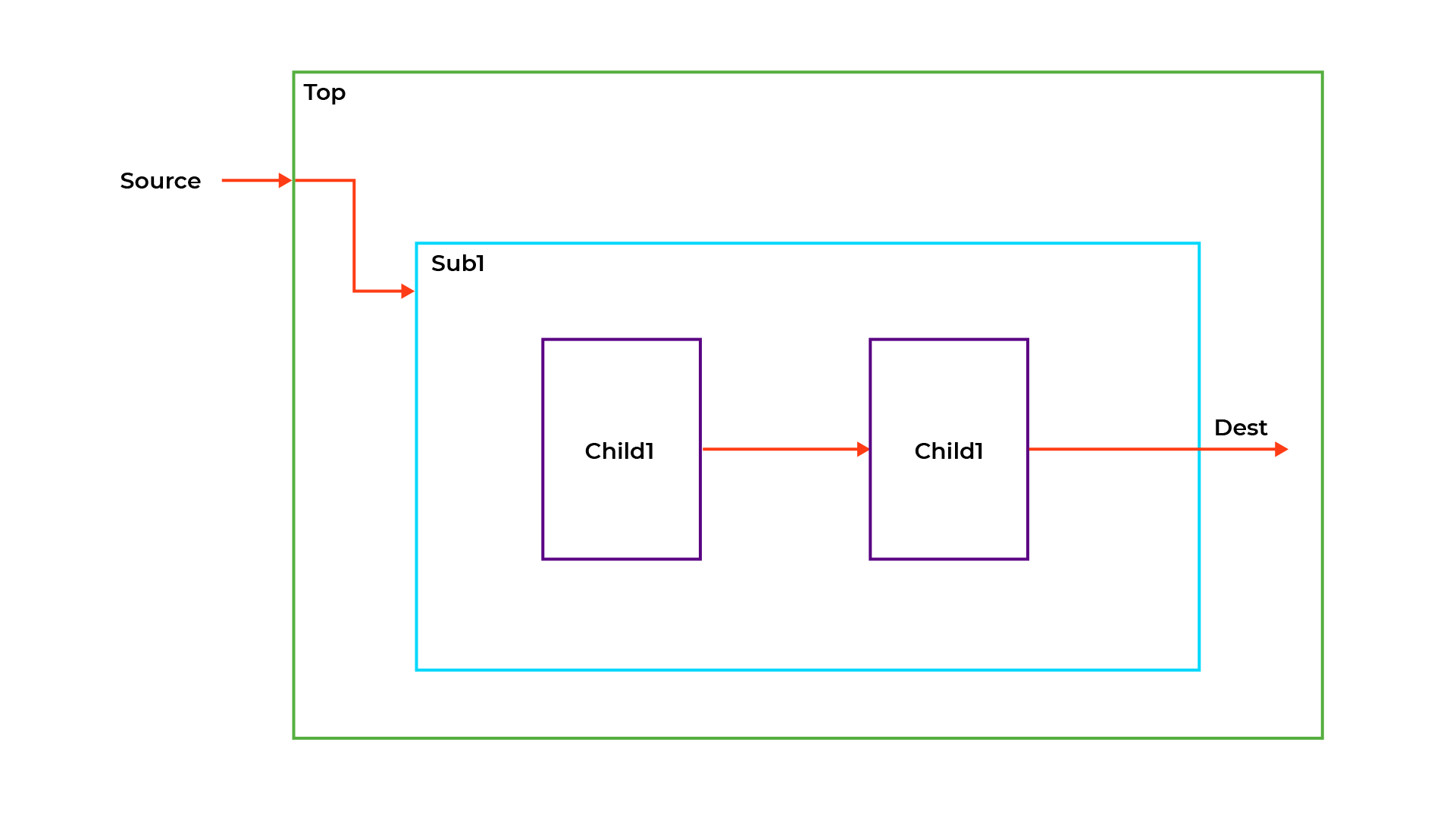
In this scenario, a signal came from a top-level source, went through two flops in a sub-module, and then got to its destination. Every flop adds a cycle of latency:
top.source → sub1.flop1 → sub1.flop2 → sub1.dest
JasperGold was used to officially check this, and the tool can generate the time-aware check directly from the connectivity map CSV file as given here:
CONNECTION, delayed_conn,, top, sub1, dest,
,PIPE, 2, top_clk, ~reset_n,,
Explanation of PIPE fields:
| Field | Description |
| PIPE | Indicates that this is a pipelined connection |
| 2 | Number of delay cycles (2 in this case) |
| top_clk | Clock domain under which the delay should be modeled |
| ~reset_n | Active-low reset signal |
| Input/output conditions | Optional fields to describe protocol or valid conditions |
From this CSV, JasperGold automatically synthesizes a time-aware assertion, like this:
source_signal |=> ##2 dest_signal);
Formal Property Verification (FPV) in Universal Verification Methodology
After checking the signal routes, we used formal property verification (FPV) to check the controller’s behavior against the design specification as part of the broader verification process. The FSM-based controller has to send config/start/stop commands, avoid conflicts, and handle reset and low-power modes correctly.
We Verified:
- FSM changes for all legal input sequences
- Timing between the config, enable, and ack signals
- Reset and recovery from low-power mode
- Only performing operations on instances when they are needed
We utilized parameterized assertions to check that all modules acted the same way.
For example:
valid_write && target_id == N |-> config_reg[N] == expected_value);
We were able to keep our code tidy, eliminate duplication, and make tests that could grow with parameterization. We also utilized assumptions to limit the solver and cover attributes to make sure that the state could be reached.
Assumptions and Guidance
- To keep proof times practical, effective use of the tools often depends on user understanding of the system and its constraints, so we:
- Made assumptions about inputs that have limits
- Used cover properties to check if a property was reachable
- Scoped assertions for each level of the FSM
Challenges Faced
- State Explosion: This is a challenging complexity problem in exhaustive analysis, so we reduced it by dividing big attributes into smaller claims.
- Proof Time: To make things converge better under limited resources, we included cover checks and bounded proofs rather than aiming for full proofs everywhere.
- Assertion Fatigue: Macros and helper functions helped us keep assertions simple and easy to read.
Results
- Before the RTL freeze, there was 100% signal connectivity
- During the first formal analysis, property checking exposed flaws early in critical controller blocks
- Assertions worked well with changes to the design
- Avoided regressions and saved time
Outcome
- Early detection of FSM flaws (edge cases, conflicting commands)
- Proofs worked nicely with RTL tweaks
- No surprises in the end
Final Thoughts
Formal verification is not merely a box to tick; it is part of a broader engineering plan that includes formal verification solutions. If there are multi-instance modules, FSM-heavy controllers, or safety-critical logic, formal verification should be a part of the regular flow because formal methods provide mathematical guarantees that reduce the likelihood of failures and improve reliability in safety-critical software systems.
Its strengths become particularly obvious when checking complicated interconnects, like the dense GPIO matrices used in automotive SoCs or general-purpose MCUs, where signal-level accuracy and configurability are particularly important. These are the points where simulation commonly misses edge cases, especially when there are pins that can go both ways. Start with structure, then apply formal techniques by focusing exhaustive analysis on the most critical blocks when full coverage is impractical due to design complexity, add parameterized assertions to make it bigger, and check both behavior and liveness.
Formal verification does not simply check for connectivity; it also rigorously guarantees correctness for every valid setup.
Know More@ https://www.einfochips.com/domains/semiconductor/
Frequently Asked Questions – Formal Verification in ASIC
1. Why is chip verification critical in semiconductor design?
Chip verification, especially complex SoC, ensures that a design functions correctly before fabrication. It helps detect design flaws, validate specifications, and prevent costly silicon re-spins during the semiconductor development process with different possible methodologies.
2. What types of connections does Jasper Gold support?
The Connectivity App handles all common connection types, including: [2]
Unconditional and constant connections.
Combinational value propagation (no latency).
Sequential propagation (with exact latencies).
Multi-cycle paths and pipeline connections across different clock domains and resets.
3. What is the main purpose of time-aware checks?
They exhaustively verify structural and temporal paths (e.g., source to destination). By tracking clock cycles and latencies, they catch bugs where a signal arrives too early, too late, or is lost entirely across System-on-Chip (SoC) IP blocks.