The Battery Management System (BMS) serves as the central intelligence of High-Voltage (HV) battery packs. It plays a significant role in the safety and efficiency of the overall Battery Storage System. Whether in electric vehicles (EVs), renewable energy storage, or industrial applications, a well-designed BMS is essential for monitoring battery health, communication with external controllers, and preventing critical failures such as thermal runaways.
In high voltage applications, the complexity of designing energy storage systems significantly increases. It is due to high cell density, which requires real-time monitoring of individual battery modules for temperature, voltage, current, and SoC/SoH estimations.
A poorly designed BMS can lead to severe consequences, including battery degradation, inefficiencies, and hazardous failures like fires or explosions, whereas a well-designed BMS can maximize battery performance, ensure safety, and enable efficient system integration. Therefore, without a reliable BMS any HV battery system cannot achieve its optimal performance and safety requirements.
Given this critical nature of HV-Battery Management System, BMS engineers must be aware of the practical challenges that can occur during the development and the entire lifecycle of the battery system. Each BMS design element comes with its own set of challenges, starting from the selection of the right design architecture to implementing robust communication protocols.
The following section covers major challenges which BMS designers and engineers need to consider:
1. Wired and Wireless BMS Architecture
The Wired BMS architecture relies on robust, shielded communication lines connecting cell monitoring units (CMUs) to the master controller. Wired systems offer established reliability and EMI immunity; their complexity increases with voltage and cell count, introducing challenges like signal integrity, connector robustness, and insulation coordination.
Wireless BMS (wBMS) architectures remove complicated wiring harnesses, increase manufacturing savings, and reduce transmission points of failure. Yet, data integrity, latency control, and cybersecurity are key challenges for wireless systems. Design considerations include low-power wireless transceivers that can handle dense electromagnetic environments while still ensuring reliable transmission of critical voltage and temperature data at the cell level, often with multiple paths for redundant communications to ensure fail-safe operations.
Both architectures are further complicated by the need to comply with functional safety standards like ISO 26262. As BMS architecture evolves from wired implementations to wireless designs, the need for accurate battery state estimation becomes even more critical, regardless of the communication method used.

Figure 1: Wired Vs Wireless BMS Architecture
2. Challenges in State of Charge (SoC) and State of Health (SoH) Estimation
SoC dictates how much energy a battery has available at the moment, while SoH is an evaluation of long-term battery degradation, which interacts with predictive maintenance and system reliability.
Figure 2 shows the changes in SoC and SoH according to charging and discharging cycles.
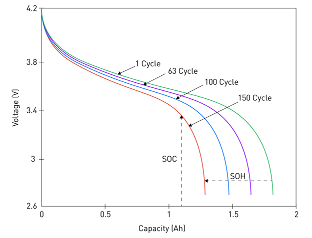
Figure 2: SoC and SoH
a. SoC estimations are challenging because battery dynamics are changing. There are various methods of estimation such as the Coulomb Counting method, the Open-Circuit Voltage method, and Kalman Filtering techniques. These techniques are efficient in their own way but have some individual limitations too.
Therefore, a blend of Coulomb Counting, Kalman Filtering, and OCV calibration is typically optimal, but designers must optimize sensor accuracy and processing efficiency in order not to induce unnecessary complexity and power consumption.
b. SoH estimation is even more challenging as it addresses long-term degradation monitoring. The Capacity-Based Method is not feasible for practical application as it stresses the battery. The accuracy of Internal Resistance Measurement is affected by temperature and SoC variations. The efficacy of the Kalman Filtering model is dependent on having good battery-aging models. Machine Learning methods are faced with challenges of computational cost, requirements of continuous learning, and demands of large training data.
A combined SoH estimation technique based on Impedance Measurement, Kalman Filtering, and Voltage Tracking provides a trade-off between real-time monitoring, long-term trend, and computational feasibility.
3. Active vs. Passive Cell Balancing

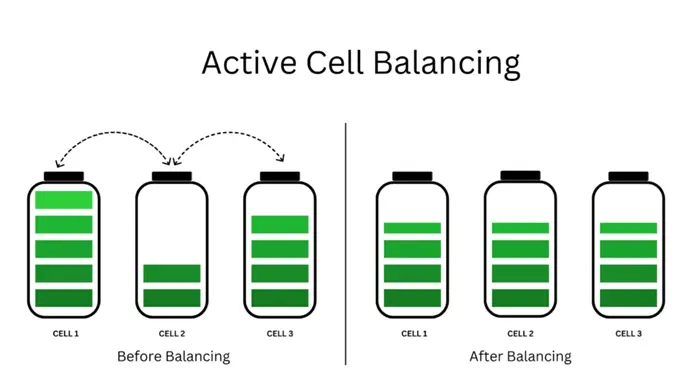
Figure 3: Active Vs Passive Cell Balancing
Cell balancing also plays a vital role in maintaining the health of a battery pack. Passive balancing utilizes resistor bleed circuits to dissipate excess charge as heat, which is a low-cost, simple, and space-efficient solution for most applications. However, it is not efficient and not suitable for high-capacity or long-life packs, as it wastes energy and cannot balance large state-of-charge (SOC) imbalances.
In contrast, active balancing transfers charge between cells via a switched capacitor, an inductor-based, or transformer-coupled circuits. While active balancing improves energy efficiency and extends the life of batteries, it comes with the cost of added design complexity. The primary challenges are the balancing speed versus circuit size trade-off, isolation between cells, thermal management of the active components, and the control strategy for deciding when to initiate balancing based on dynamic operating conditions. Designers must also ensure that the active balancing circuits do not interfere with the main power path or communication signals, particularly in high-voltage systems with strict EMI specifications.
4. Actuators Control and Monitoring
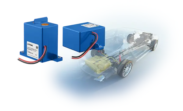
Figure 4: Actuators Control
Actuators in an HV BMS, such as contactors, pre-charge circuits, cooling system pumps, or safety disconnects, must be accurately and reliably controlled. The primary challenge is the coordination of actuators under various operational and fault conditions to ensure safe pack operation. Control strategies must consider the actuator state monitoring (via position sensors or current feedback), response time, and failure diagnostics.
Besides, the operation of high-voltage contactors involves significant design challenges such as inrush current limiting, arc quenching, and welding of contacts. Actuator status implementation in the fault-handling logic of the BMS, is important especially for functional safety compliance. Actuator drivers must be galvanically isolated, allow real-time monitoring, and be transient voltage event-robust so that improper operation does not compromise system safety or damage components.
5. Communication Protocols and Master-Slave Architecture
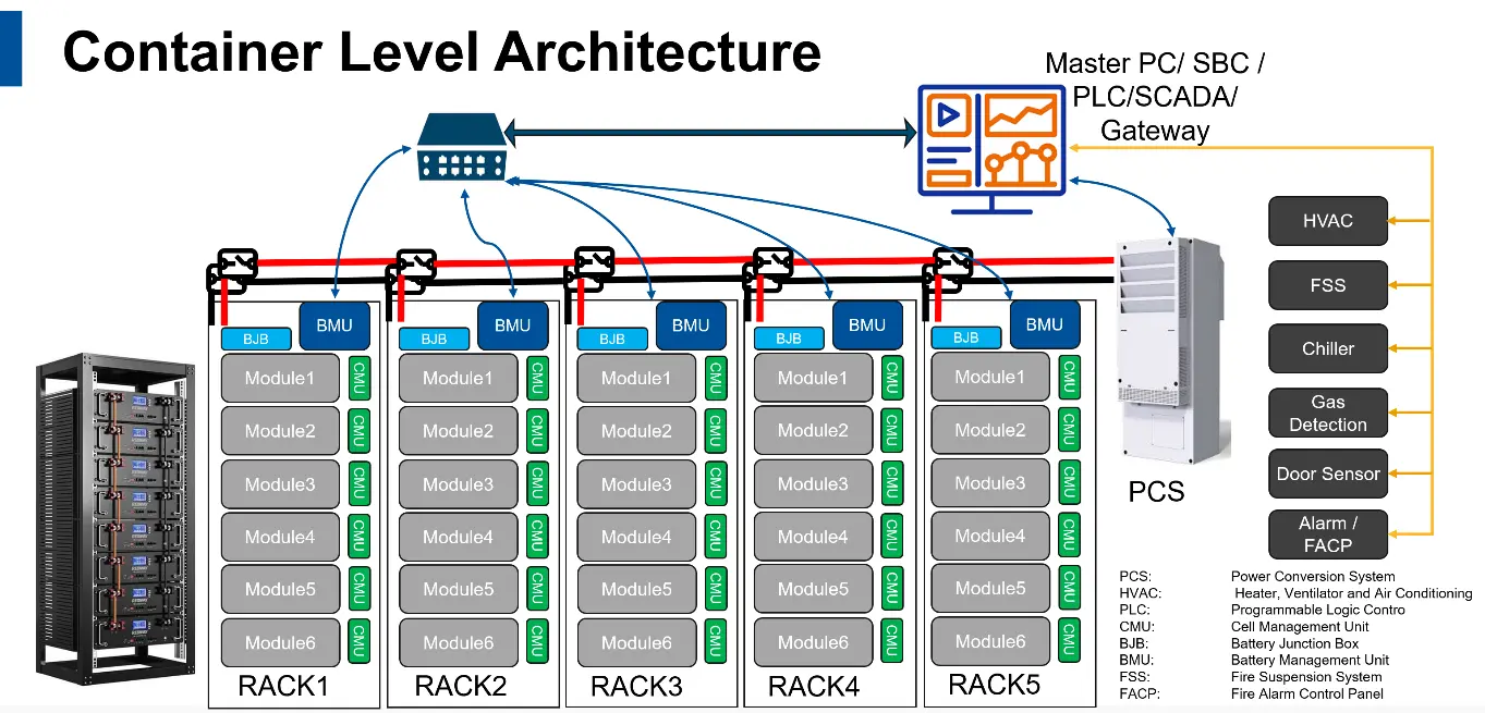
Figure 5: Master Slave architecture
A high-voltage BMS typically adopts the Master-Slave architecture with multiple slave CMUs monitoring the cell voltages, temperatures, and balance status and reporting the same to a centralized master controller. This top-down approach provides challenges in data aggregation, fault isolation, and control of redundancy.
Protocols employed to communicate—such as CAN, CAN FD, SPI, or Ethernet—should be selected based on data rate requirements, tolerance to EMI, and system expandability. For example, CAN has reliable performance but is not suited to bandwidth in large packs, whereas Ethernet-based items provide a higher throughput at the expense of more sophisticated isolation and error-checking.
Designers must also account for node synchronization, measurement, timestamping, and security (especially in automotive and grid-connected systems). Diagnostic coverage, fault tolerance, and watchdogs or heartbeat messages are crucial to preventing system-level failure due to communication failure.
6. Product Safety and Functional Safety Standards and Compliance
A high-voltage BMS design involves two major safety issues – product safety and functional safety. Product safety ensures the system’s physical resilience against mechanical vibrations, thermal stress, and electrical hazards. This includes choosing the right materials, insulation, and mechanical design to prevent injury under foreseeable fault conditions.
Functional safety focuses on how the BMS operates during faults like thermal runaways, communication loss, or sensor failures. It ensures that the system can detect the fault and respond accordingly by reducing the risk of unsafe behavior. There are certain standards like IEC 61508 and IEC 60730 Annex H which are widely used to govern these behaviors.
The best practice is to align with IEC 61508 for hardware/system-level safety and use IEC 60730-1 Annex H for software control. This dual compliance/standard strategy enables global certification and supports robust development lifecycles and market readiness.
7.Emerging Regulations in Battery Management Systems and Associated Design Challenges
New regulations are pushing BMS design toward greater transparency, safety, and sustainability. For instance – the EU Battery Regulation 2023/1542 introduces a “Battery Passport” to enable real-time traceability and carbon footprint reporting by 2027. This demands secure data handling, cloud integration, and traceable logging of battery life.
In the U.S., a fragmented regulatory framework adds complexity, by demanding that the BMS architectures are flexible and adaptable to varying environmental, transport, and recycling rules.
International standards like UN/DOT 38.3, IEC 62619, and UL 1973 require design provisions for thermal safety, fault detection, and safe transport. Regulations around second-life batteries and recycling targets further add to the need for SoH tracking and modular designs that ease reuse.
To meet these demands, the BMS must support OTA compliance updates, sustainability metrics, and secure data collection, all without compromising performance or scalability.
8. Cybersecurity Challenges and Implementation in Battery Management Systems (BMS)
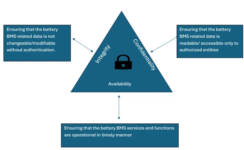
Figure 6: BMS Cybersecurity Fundamentals
The BMS systems are now connected via IoT, AI, and Cloud platforms. Cybersecurity has become a critical design concern. Threats like firmware tampering, denial-of-service attacks, and data breaches can compromise safety and performance.
To mitigate these risks, robust strategies must be employed—including end-to-end encryption, secure firmware updates, intrusion detection, and multi-factor authentication. Blockchain-based data integrity is increasingly being explored for lifecycle traceability.
However, challenges like limited processing resources, latency introduced by encryption, and adherence to evolving standards (e.g., ISO/SAE 21434, IEC 62443) must be addressed. Future-ready BMS designs will require embedded cybersecurity from the beginning, supporting both regulatory compliance and operational resilience.
Conclusion
BMS engineers and system integrators must address these challenges. They should keep these design considerations in mind to develop a robust BMS solution for EVs, renewable energy storage, or any industrial applications.
With a dedicated BMS Center of Excellence (CoE), eInfochips offers high-voltage BMS development services for varied industry applications such as electric vehicles, energy storage systems, renewable energy, and industrial equipment, etc. Utilizing in-house labs and infrastructure, eInfochips helps customers with the turnkey development of BMS hardware, embedded software, industrial/mechanical design, software engineering, functional safety assessment, cybersecurity implementation, and compliance with regulatory standards and certifications.
To fast track your BMS development journey, eInfochips has built a production-grade HV BMS reference design based on the NXP S32K3 MCU, compliant with IEC 61508 and IEC 60730 standards.
For further information, please visit our whitepaper –
Authors


Amr Elwakil Mohamed Abdelrazek