The automotive industry is undergoing a monumental shift. From Advanced Driver-Assistance Systems (ADAS) to electrification, software has become the heart of modern vehicles. As a result, automotive software development is facing unprecedented complexity, making it difficult to manage systems using traditional development methods.
Model-Based Development (MBD) is a technique that can be used to address such complexity in automotive software development. It is a process for designing and simulating embedded control systems using graphical models. With this approach, engineers can create, test, and implement embedded systems more quickly and accurately.
According to Mathworks’ industry case study – using the Constructive Cost Model (COCOMO), their customer determined they could significantly reduce costs by transitioning from traditional development methods to Model-Based Design. The company reduced project costs from $6 million to $3 million for a 50,000-line-of-code software project – an approximate saving of 50%. These savings were attributed primarily to improved requirements analysis, early and continuous testing, and automated code generation.
Traditional Development Process vs. Model-Based Design
Each step of traditional automotive software development is usually completed independently using several tools and several manual handovers. This leads to risks and inefficiencies. If a Model-Based Design strategy is not used, it leads to delays, mistakes, and integration issues, from gathering system requirements to operational deployment.
While system designs are made with basic diagramming tools, requirements are frequently written using programs like IBM® DOORS® or Microsoft® Word®. This approach makes it difficult to manage the changing requirements. Additionally, domain-specific tools are used to build subsystem designs, thereby limiting system-level evaluation until the hardware or software is implemented.
These designs are then manually converted into code that can lead to human error. These errors can occur at various development stages but many times they only get detected during the testing phase. The lack of an integrated toolchain and delayed validation—contribute to longer development cycles and inflated budgets.
Here’s the breakdown of the traditional development process:
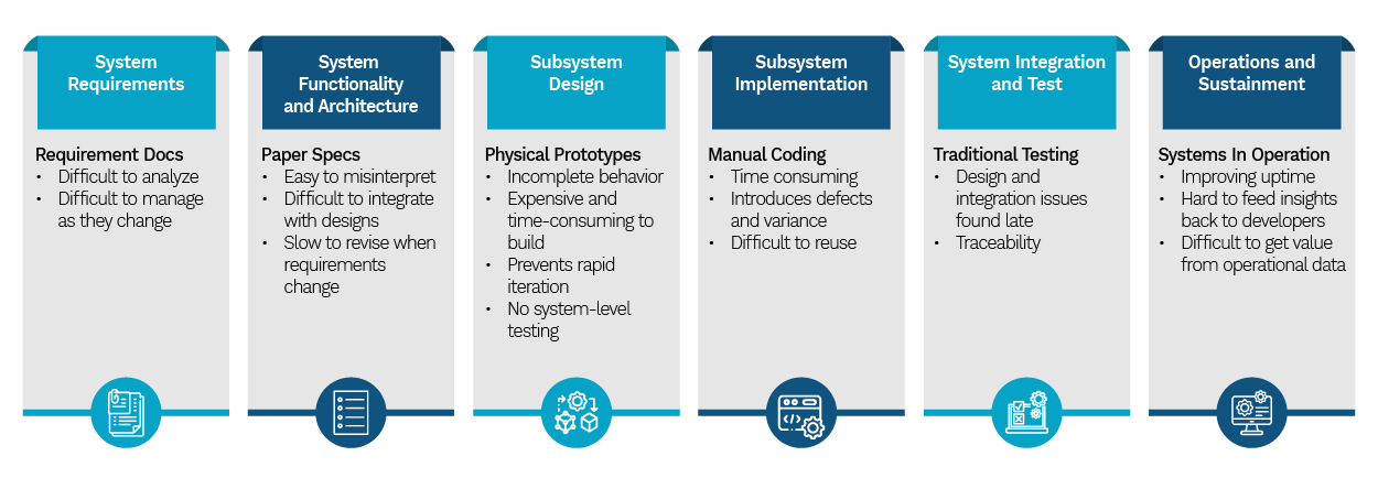
Image Source: MathWorks white paper ‘measuring-ROI-of-model-based-design’
MBD integrates system models throughout the entire development lifecycle. Like traditional approaches, it begins with the same fundamental requirements; however, instead of relying on static textual documentation, it transforms these requirements into executable models that represent the system’s architecture and behavior. This enables a system-level model to function as a living specification throughout development.
Engineers can identify interface or logic problems by using tools like MATLAB® and Simulink® to do system-level simulations. After this, design verification, production-grade code and related test cases are automatically generated using the models, eliminating the errors generated during manual coding.
Additionally, testing can start as early as the requirement stage, enabling teams to use model simulation to confirm the design intent. This leads to earlier detection and resolution of defects, ultimately reducing the rework and cutting down the overall development costs.
Let’s look at the software development process using Model-Based Design:
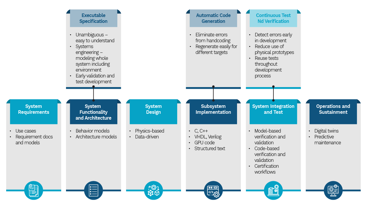
Image Source: MathWorks white paper ‘measuring-ROI-of-model-based-design’
A Migration Journey to Model-Based Design
Traditional development techniques often find it difficult to meet modern demands for efficiency, quality, and time-to-market as embedded systems become more complicated. By putting system-level models at the center of the development process, MBD provides a revolutionary approach. The migration journey involves a structured shift from manual, document-driven workflows to a model-centric methodology. Engineers can methodically implement MBD and realize its full potential throughout the embedded product lifecycle by following these steps:
- Modeling
- Simulation
- Rapid prototyping
- Embedded deployment
- In-the-loop testing
1. Modeling
System modeling in MBD involves creating mathematical and visual representations of dynamic systems to show how they react to inputs over time. To effectively design control, signal processing, and communication systems, engineers utilize graphical environments with block diagrams and state machines.
These models could be discrete dynamics (like software on microcontrollers) or continuous dynamics (physical systems like cars or turbines)—both are combined in many real-world models.
2. Simulation
In MBD, numerical integration is used to model continuous systems. There are two primary solver types: fixed-step and variable-step. Variable-step solvers adaptively modify the time step for increased accuracy, whereas fixed-step solvers run at fixed intervals.
3. Rapid Prototyping
In rapid prototyping, engineers use control or signal processing models to create code, which is then deployed to a high-speed, real-time prototype system. Through I/O interfaces (like memory pods or emulators), this system is linked to the real hardware configuration, such as an engine or motor.
The goal is to test and fine-tune control algorithms directly with real world inputs and outputs. During lab or field testing, parameters can be changed at any time.
4. Embedded Deployment
Following the completion of fast prototyping, attention turns to developing a comprehensive software design that converts the controller model into an executable specification, made for embedded hardware.
The model is improved to ensure it functions well on the target embedded system (such a microcontroller or ECU). This improved approach is used to automatically build embedded code that is optimized for performance and memory efficiency. After that, this code is deployed to the actual embedded processor and incorporated into the production software package.
5. In-The-Loop Testing
To combine production code and hardware into MBD, one can compare dynamic outputs of models with data collected through processor-in-the-loop and software-in-the-loop test or with the data measured in test labs, using the logging tools or data inspector.
- Software-in-the-loop (SIL): The auto-generated code is tested in a simulated environment to ensure its behavior matches the model. It is crucial for identifying discrepancies before integrating the code with hardware.

Software-in-the-loop Testing - Processor-in-the-loop (PIL): This testing is similar to SIL in that it also executes the production code for the controller. However, the code executes an instruction set simulator or on the actual embedded processor, so that it verifies the code behavior on the actual target. As with SIL, PIL testing is a non-real-time execution scenario as shown in the figure below:

Processor-in-the-loop (PIL) - Hardware-in-the-loop (HIL): In this testing, the code is also generated for the plant model. It runs on a highly deterministic, real-time computer. Rapid prototyping is often a design or development activity, HIL serves as a final lab test phase before the final system integration and field tests commence.

Hardware-in-the-loop Testing


Tools
Essential Tools for Modeling and Simulation
- Simulink® is widely used for block diagram-based graphical modeling, simulation, and analysis of dynamic systems.
- MATLAB® offers technical computing, data analysis, and mathematical integration features; it is frequently used in combination with Simulink® for data processing and model simulation.
Tools for Specialized Model-Based Design
- Stateflow® is a tool for creating and modeling control logic and state machines in Simulink® models.
- Simulink® Verification and Validation™ makes it possible to verify Simulink® and Stateflow designs, analyze model coverage, and trace requirements.
- Polyspace Static Analysis performs static code analysis to detect run-time errors, ensure compliance, and assess code quality, particularly in code generated automatically from models.
- Model Advisor provides automated model checking and diagnostics to guarantee adherence to modeling best practices and guidelines.
Other MBD Integrations and Components
- Tools for Processor-in-Loop (PIL) Simulation used to validate and verify embedded software by executing code on real processors and comparing the results with model simulations.
- Tools for Automatic Test Case Generation included into the MBD process for quick and precise validation and verification cycles.
Applications for Model Based Development
MBD is essential for innovation in a variety of sectors, including industrial and automotive systems.
- ECU Development: MBD is used to create and simulate control algorithms for fuel injection, brakes, thermal management, pollution control, and other systems.
- Advanced Driver Assistance Systems (ADAS): Models replicate and validate use cases like adaptive cruise control, automated parking, and lane-keeping assistance.
- Electric and Hybrid Vehicles: MBD enables the design of battery management systems, powertrain control, and energy optimization for electric and hybrid vehicles.
- Real-Time Control Systems: MBD enables the development of embedded software for devices including robotics, industrial controllers, and Internet of Things sensors.
- Firmware Development: Models reduce manual coding errors by producing microcontroller code that is suitable for production.
- Automatic Code Generation: MBD tools such as Modelica or MATLAB®/Simulink®, reduce manual coding errors by generating production-ready code from models.
- Verification and Validation: Models enable early testing through simulation, ensuring compliance with requirements before implementation.
eInfochips offers end-to-end Model-Based Development services for control algorithms and embedded software development across various applications. We have expertise including modeling and simulation using MATLAB®/Simulink®, embedded code generation in C/C++, automation and validation using tools like LabVIEW and VeriStand. Additionally, we are skilled in integrating Vector VT for ECU HIL testing solutions and Speedgoat for real-time system validation.
Our development cycle covers:
- Model-in-the-Loop (MIL) for software requirements and design.
- Software-in-the-Loop (SIL) for functional verification.
- Hardware-in-the-Loop (HIL) testing for hardware integration and validation.
- Embedded firmware development and integration with RTOS, legacy code, and I/O drivers.
We also provide multi-platform deployment across FPGAs, DSPs, and microcontrollers, enabling scalable motion, process, and automation control system solutions.