The role of electronic systems in the automotive industry is continuously expanding. As the number of electronic functions increases, so do the number of ECUs in the vehicle. This increase in ECUs and electronic functions results in the associated software becoming more complex and expansive.
The concept phase serves as the initial planning and requirements definition stage in the V-Model, establishing system goals, conducting hazard analysis, and setting the foundation for subsequent design and safety activities.
According to Markets and Markets, the global automotive software market is projected to grow to USD 37 billion by 2025, from USD 16.9 billion in 2020, at a CAGR of 16.9%. Statistics show that software plays a vital role in various vehicle functions, and this role is expected to proliferate in the future.
As a mission-critical industry, the automotive development process must adhere to regulatory standards such as ISO 26262 and ASPICE to minimize the risk of failure. Following standard development procedures can have a positive outcome on the success of automotive functions and software. V-Model is one of the widely used software development processes in the automotive industry.
To put it simply, V-Model (where V stands for verification and validation) splits the development process into two parts – the left arm of the V consists of requirement analysis, function design, and software development, while the right arm concentrates on the verification and validation activities followed by the release. The V model’s structure, with its sequential phases, facilitates systematic development, early defect detection, and traceability. The V model’s structured approach is a traditional, rigorous framework that supports quality and compliance, and can be combined with agile practices for greater flexibility. The V-Model also provides strong project management and process management benefits, helping organize and control the automotive software development lifecycle. The V-model is an extension of the waterfall methodology, and it emphasizes testing, particularly the need for early test planning. Each phase of the V-model aligns with the ASPICE standard and helps in clearly defining a life cycle.
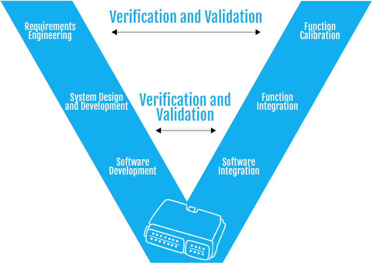
Understanding the V-Model process
Requirements Engineering: This is the first step in the V-model process and entails establishing and documenting requirements. It includes clearly defining and noting the task/s that the automotive function/feature will perform and how. The success of the design and development phase depends significantly on this phase being well executed. Clearly defining system requirements at this stage is crucial to ensure safety, compliance, and reliability throughout the project.
However, many a time, the requirement document may not contain details about the implementation. Since the development process follows this phase, it is best to involve the development team while preparing the requirements document to ensure clarity. Systems engineering serves as the guiding methodology for this structured development process, supporting traceability and validation in complex automotive projects.
System Design and Development: The next step is the actual design and development of the function/feature for which the requirement was gathered in the first phase. In the development phase, the functionalities are designed and tested using the model-based development environment. The function/functionality needs to be tested as it is being developed, ensuring that bugs and errors are fixed early on. In automotive applications, embedded systems are often safety-critical, requiring systematic development and rigorous testing to meet industry standards.
In the model-based development environment, simulation tools such as MATLAB/Simulink can simulate real-world scenarios. The potential bugs and errors are highlighted and rectified during this phase. These tests are called Model in the Loop (MIL) since the testing is done in a controlled environment using models. Once the development process and testing are complete and the results are satisfactory, the model – a block diagram – is then sent to the software development team.
Developing Software: The software piece is created according to the model. There may be different versions of the software depending upon the use case. Model-based design tools can generate automatic code; most of the hand (written) codes are written in C language, and most ECUs are also developed using C. The software development input can either be in the form of the model or a requirement document, both of which give a detailed description of the function/feature.
The document for software development contains details regarding the software architecture, its modularity, the number of functions in the module, its periodicity, and a flowchart of the entire software, among others. Unit testing is performed during this phase to detect defects early and ensure the reliability and safety of the software in safety-critical environments. Once the software development process and testing are complete, we progress to the next phase.
Software Integration and Function/Feature Integration: Since there are different ECUs, most may have their own control software. The engineer combines all the software modules during the software integration phase and checks the interaction between them. Integration testing is a key activity at this stage to ensure proper interaction between software modules and to detect integration issues early. System integration involves combining various subsystems and validating their interactions to ensure overall vehicle functionality and compliance. The impact on the legacy code and other software modules is also monitored. Again, the testing in this phase is done with the help of simulations using Hardware in a Loop (HiL) environments.
System testing follows integration, where the integrated system is tested for overall functionality, safety, and compliance with regulatory standards. The engineer then needs to assess whether the newly integrated function affects any other modules’ functioning. However, the testing here is done in a physical environment (in-vehicle test). The most important aspect of testing, in this case, is ensuring that the implementation is done correctly, with no flaws or unwanted consequences.
Acceptance testing serves as the final validation step to ensure the system meets all specified requirements before deployment. Final testing is conducted as a comprehensive check before the system is released, confirming readiness for production and usage. The validation phase encompasses verification and validation activities to confirm that the complete system is ready and all components work together as intended.
Therefore, a test scenario must be defined and prepared to test the function in the vehicle. Next, the ECU is connected to a computer loaded with the prescribed tools via different communication protocols. This validation process helps in confirming that the product can perform as required. The integration phase is followed by function calibration; this involves fine-tuning the software parameters to enable top field performance.
Advantages of the V-Model in Automotive Software Development
Structured Approach:
The V-Model provides a structured framework for automotive software development. It synchronizes the phases of development, testing, and validation, ensuring that each requirement is meticulously addressed, and every defect is promptly identified and rectified.
Early Validation:
An eminent advantage of the V-Model is its emphasis on early validation and testing. This early verification process mitigates the risk of late-stage defects, potentially saving substantial costs while ensuring the safety and reliability of automotive software.
Regulatory Compliance:
The automotive industry is tightly regulated, with stringent safety and quality standards such as ISO 26262 for functional safety. The V-Model’s attention to documentation and traceability greatly assists in demonstrating compliance with these rigorous requirements.
Enhanced Quality:
The integration of validation and verification throughout the development process facilitates the delivery of high-quality software.
Challenges of the V-Model in Automotive Software Development:
Rigidity:
The V-Model’s linear and somewhat inflexible structure may not always align with the demands of agile development practices, making it challenging to adapt to rapidly evolving requirements or customer feedback.
Lengthy Development Cycles:
The comprehensive testing and validation phases incorporated in the V-Model can potentially extend the development timeline. This can pose a significant challenge in an industry where swift time-to-market is imperative.
Costly Documentation:
The substantial documentation required by the V-Model can lead to increased overheads in terms of time, resources, and expenses. Managing this documentation efficiently can be a formidable challenge.
Talent and Training:
To effectively implement the V-Model, automotive companies must ensure that their teams possess the requisite expertise and training. Nurturing and maintaining this expertise can be a prolonged challenge.
Emerging Trends in Applying the V-Model in Automotive Software Development:
Agile Integration:
To circumvent the rigidity of the V-Model, many automotive software development teams are increasingly incorporating agile practices. This amalgamation, often referred to as “Agile-V,” allows for greater adaptability while retaining the V-Model’s structured approach.
DevOps Adoption:
The adoption of DevOps, which underscores collaboration and automation between development and operations teams, is gaining momentum in automotive software development. This trend streamlines software deployment and updates, enhancing efficiency.
Continuous Verification and Validation:
Automotive companies are progressively embracing continuous verification and validation practices. This approach involves testing and validation as ongoing processes throughout the software development lifecycle, rather than distinct phases.
Model-Based Development:
The utilization of model-based development tools and techniques is on the rise to enhance the efficiency of the V-Model. These tools aid in creating a higher level of abstraction and automation, simplifying development complexity.
Autonomous Vehicle Development:
The development of autonomous vehicles challenges the boundaries of the V-Model. Given the complexity and safety-critical nature of the software involved, it demands even more rigorous testing and validation.
Conclusion
The V-Model remains a valuable methodology for automotive software development, offering a structured approach, early validation, and regulatory compliance advantages. Nonetheless, it also presents challenges related to rigidity, prolonged development cycles, documentation, and talent requirements. In a rapidly evolving automotive industry where software is paramount, the V-Model is adapting to address these challenges through the integration of agile practices, DevOps adoption, continuous verification and validation, model-based development, and a keen focus on autonomous vehicle development. As the importance of software in vehicles continues to grow, the V-Model will evolve to meet the dynamic demands of this industry.
The V-model is simple and easy to use, but it is also rigid and does not allow for any shortcuts in case of an emergency. It helps in clearly defining a cycle and efficient implementation if the requirements are clearly established in the requirement gathering phase. A strong team with adequate knowledge and experience aids success.
eInfochips is an ISO 26262 and ASPICE certified systems and software partner for various automotive companies across the world. We have experience in successfully developing automotive systems and subsystems for our clients. To know more about our expertise, please get in touch with us.