Introduction To AC3
AC3 is an audio data compression technology by Dolby Laboratories. It is also known as Audio Codec 3. The AC3 algorithm can encode multiple audio channel formats into a single low-rate bitstream. The configurations supported by Dolby AC3 are:
- Conventional mono channel.
- Conventional Stereo Channel (Mono+Mono or Stereo), and
- Surround sound consists of stereo channels and two surround channels (left and right), and a subwoofer, all of which are put together from the 5.1 Channel configuration.
The six-channel configuration consists of the left channel, center channel, right channel, left surround, right surround, and subwoofer. The AC3 bitstream specification allows sampling rates of 48 kHz, 44.1 kHz, and 32 kHz. It supports data rates ranging from 32 kbps to 640 kbps.
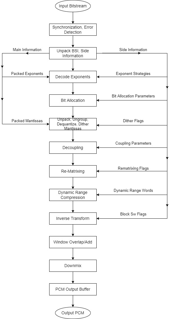
AC3 Decoder
The decoder must synchronize with the encoded bit stream, check for errors, and de-format the various types of data such as the encoded spectral envelope and the quantized mantissa. The bit allocation module is designed to calculate the number of bits required to encode each transform coefficient mantissa value on the encoder side. At the decoder, the bit allocation module execution results in unpacking and de-quantization of the mantissa values. Decoding of the spectral envelope results in the exponent’s values. Thereafter, the exponents and mantissas are converted back into the time domain to extract the decoded PCM time samples.
Synchronization and error detection
When a sync pattern is detected, the decoder may be estimated to be in sync and one of the two Cyclic Redundancy Check words (crc1 or crc2). A 16-bit sync word is used so that there’s a low probability of a false frame detection. The first CRC (crc1) covers 5/8th of a frame, hence the CRC1 results will be available only after receiving the 5/8th of a frame. Hence, it is preferable to check the entire frame size using crc2 after the entire frame is received. If either of the CRC’s (crc1 and/or crc2) comes out to be good, the decoder shall be assumed to be in sync, and hence, one may proceed with decoding and reproduction of the audio data.
Unpack BSI, side information
The BSI (BitStream Information) is the process of unpacking of various types of information in the bit stream received at the decoder. The BSI consists of a 5-bit, bit-stream identification information, 3 bits of bit-stream mode indicating the type of service that the frame conveys, 3-bit audio coding mode, indicating the channel array configuration. Apart from this, there are bits representing the surround mix levels, the surround modes, LFE (Low Frequency Effects) modes, dialogue normalization mode, language codes, audio production information and other meta data as well.
Decode exponents
At the AC3 encoder level, the exponents are represented in a floating-point format. In the encoded data stream, the floating-point coefficients are transmitted in exponent-mantissa format. At the decoder, the exponents and mantissas are unpacked and decoded using the side information.
Bit allocation
The bit allocation module uses the human hearing threshold model to compute the number of bits required for each transform coefficient mantissa. The bit allocation module takes the decoded exponents, and the bit allocation side information as input. The output of the bit allocation module shall be a set of bit allocation pointers (baps) (one bap for each coded mantissa). The bit allocation indicates the quantizer used for the mantissa, and the number of bits used for each mantissa, in the bit-stream.
Process mantissas
Most of the bits of an AC3 data stream represents the quantized mantissas. The bit allocation pointers represent quantizer levels and the codeword lengths used extracting mantissas. For the bit allocation pointer ranging from 6 to 15, the quantization type is asymmetric, whereas for values 1 to 5 the quantization type is symmetric. Each mantissa is quantized to a level of precision indicated by the corresponding bit allocation pointer.
De-coupling
As the human ears are not sensitive to high frequency components, this property of human ear is used for compressing the data further by the AC3 data compression. When coupling is enabled, the high frequency components of each channel in the bitstream are added to the coupling channel. At the decoder the reconstruction of the high frequency components (exponents and mantissas) of each coupled channel is performed. Within each coupling band, the coupling channel coefficients (exponent and mantissa) are multiplied by the individual channel coupling coordinates.
Rematrixing
The AC3 makes use of high correlation components of channels for the compression of data to reduce the output bitrate. Instead of coding each of the original channels, the sums and differences of the correlated channels are coded. Hence, for a stereo channel, if both channels contain the same data, the left channel shall contain the data and the right channel shall contain zeros, effectively making the right channel require minimal bits to encode, thus helping decrease the output bitrate.
Dynamic range compression
A dynamic range control value may be included in the bit stream, for each block of data in the audio bitstream. The decoder will use this value to change the magnitude of the coefficient (exponent and mantissa)
Inverse transform
The inverse transform is used for converting the frequency domain data back to the time domain samples using IMDCT (Inverse Modified Discrete Cosine Transform) technique.
Window, overlap/add
Windowing is applied on the individual blocks of time samples for smoothening out of the output time signal. The two adjacent blocks are overlapped and added together to reconstruct the final continuous-time output PCM audio signal.
Downmixing
Downmixing is used when the number of channels required at the decoder output are less than the number of channels available in the encoded in the bit stream. For e.g, if the encoded bitstream contains Left Channel, Right Channel, Center Channel, Left Surround Channel, Right Surround Channel and LFE Channel and if the instrument is capable of only playing stereo (decoded output can only be played on two speakers), the downmixing is required. The Left Channel and the Left Surround Channel and some components of the Center Channel are summed together to reconstruct the Left channel of the stereo mode and the Right Channel and the right Surround Channel and some component of the Center Channel are summed together to reconstruct the Right channel of the Stereo mode.
PCM output
The Output buffer of the AC3 decoder channel shall contain the PCM output samples at the defined sampling rate.
Applications of Dolby Digital Decoder
- Home Theater Systems:
- Dolby Digital is a standard in home theater systems, providing a multi-channel audio experience. Home theater receivers and soundbars often feature Dolby Digital decoding to deliver immersive audio for movies, TV shows, and music.
- DVD and Blu-ray Players:
- Dolby Digital is a common audio format for DVDs and Blu-ray Discs. The decoder is used in these players to provide high-quality surround sound for movies and other video content.
- Streaming Services:
- Many streaming platforms use Dolby Digital to transmit surround sound audio over the internet efficiently. This ensures a consistent and immersive audio experience for users watching movies or TV shows on streaming devices.
- Broadcast Television:
- Dolby Digital is used in HDTV broadcasts to deliver high-quality audio. It enhances the audio experience for viewers watching television programs, live events, and sports broadcasts.
- Gaming Consoles:
- Gaming consoles often support Dolby Digital for in-game audio. This technology enhances the gaming experience by providing spatial audio cues and realistic sound effects.
- Digital Cable and Satellite TV:
- Dolby Digital is commonly used in digital cable and satellite TV broadcasts. It allows for the transmission of multi-channel audio, improving the overall audio quality for viewers.
- Media Players and Set-Top Boxes:
- Media players and set-top boxes, such as those used for streaming or cable services, may incorporate Dolby Digital decoding to ensure high-quality audio output for users.
- Digital Audio Broadcasting (DAB):
- Dolby Digital is utilized in digital radio broadcasting to provide a high-quality audio experience for listeners.
- Cinema Sound Systems:
- Dolby Digital is used in cinema sound systems to deliver multi-channel audio in movie theaters, contributing to a more immersive cinematic experience.
- Car Audio Systems:
- Some high-end car audio systems feature Dolby Digital decoding, providing a premium audio experience for in-car entertainment.
Conclusion
The AC3 audio coding technology is being used in the following standards namely: Blu-Ray Compression Technology, DVDs, Miracast, and DivX and was developed by Dolby Digital Laboratories. It is being used in the Automotive domain for vehicle-audio systems and Home Audio Entertainment Systems. It can be implemented on high-end microcontrollers and low-end DSPs with low power consumption and low memory availability.
eInfochips provides Product Engineering Services in the DSP domain in implementing, porting, and optimizing both audio and video codecs for a multitude of microcontrollers and microprocessors for automotive as well as home infotainment domains. For more information, please connect with us today for Embedded software development services.