What is a Cadence Coverage Tool?
Ensuring thorough coverage in design verification is crucial. Traditional metrics are used to build confidence and assess verification quality. However, reaching coverage targets can be challenging, especially for complex System-on-chip (SoC) or Intellectual Property (IP) designs. This is where Cadence IMC (Incisive Metric Center) comes in handy.
Cadence IMC is a powerful tool that offers various coverage commands to simplify and speed up the coverage closure process. In this article, we’ll delve into some less-known but highly effective coverage commands supported by Cadence IMC and how they can revolutionize your verification efforts.
This article describes some powerful cadence coverage switches with detailed steps to use them along with relevant examples and additional key features.
Powerful Cadence Coverage Commands
1. Smart Exclusions in Toggle Coverage
In design verification flow, during the coverage closure phase, toggle coverage exclusion activity tends to consume more time and requires manual efforts for excluding the signals. If the same signal is required to be excluded from numerous instances/modules, for example, we must manually exclude the signal from each instance/module where it is used. It is possible to avoid this unnecessary activity of manually excluding the signal from every instance/module by using any of the commands described below:
- set_toggle_excludefile
- set_toggle_smart_refinement
set_toggle_excludefile
Introduction – This command is used to efficiently exclude toggle coverage of the mentioned signals from the design. Signals that are to be excluded must be listed in a file and passed to the command.
Syntax – set_toggle_excludefile [-nolog] [-bitexclude] <file>
The command (set_toggle_excludefile) must be passed in CCF, where <file> is the file name in which the signals that are to be excluded are listed. At the end of the successful simulation, the tool (IMC) creates an output log file (toggle_exclude.log) in which the excluded files are listed. If the ‘-nolog’ option is passed, then the output log file is not created. Option ‘-bitexclude’ is used when we require the exclusion of bit(s) from vector signals.
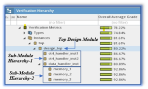
Example – Figure 2 depicts the design hierarchy. Assume that some signals are required to be excluded from the design. As a result, the command depicted in Figure 1 is executed in CCF.
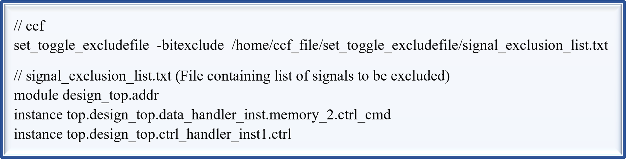
Exclusion analysis – In the signal_exclusion_list.txt file, we have passed three signals for exclusion.
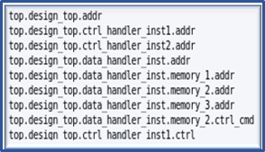
- module design_top.addr – This excludes the addr signal from the design_top module. As shown in Figure 3, in every submodule where the addr signal is passed, it gets excluded as addr signal is port signal, and exclusion is done based on connectivity (top-down/bottom-up).
- instance top.design_top.data_handler_inst.memory_2.ctrl_cmd – This excludes ctrl_cmd signal only from instance memory_2 and not from memory_1/3, as ctrl_cmd is the internal signal.
- instance top.design_top.ctrl_handler_inst1.ctrl – This excludes ctrl signal from the instance ctrl_handler_inst1 as shown in Figure 3.
Note – If the excluded signal is a port signal, then all the other signals that are connected to the excluded signal (via instantiation) are excluded, as the connectivity of the excluded signal is traced within the hierarchy (top-down/bottom-up). This is only applicable to the input port signal while the output port signal and internal signal do not have the connectivity tracing flow.
set_toggle_smart_refinement
Introduction – This command is used to smartly exclude signals for toggle coverage in the IMC Tool. Once you pass the command in CCF, then, the ‘Exclude Smart’ option is available for exclusion in the IMC tool. This option in IMC automatically traces the connectivity and excludes the signals that are connected to the excluded signal. If this command is not mentioned in CCF then you can’t avail of the ‘Exclude Smart’ option for toggle coverage.
Syntax – set_toggle_smart_refinement
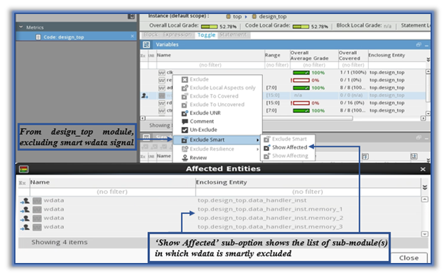
Example – In Figure 4, the smart exclusion is created for wdata in the design_top module. So, now wdata is excluded from the design_top module and from all the submodules where wdata is connected to. ‘Show Affected’ sub-option opens the ‘Affected Entities’ window that shows the list of submodules where wdata is excluded.
Note – For toggle coverage, in IMC ‘Exclude Smart’ option is only applicable to input port signals while output port signals and internal signals can’t be smartly excluded. You don’t require any command in CCF for smart exclusion in functional coverage as the ‘Exclude Smart’ option is available by default for it.
So, if you have to do manual toggle exclusions on a huge scale, then, set_toggle_excludefile/set_toggle_smart_refinement commands can come to the rescue. Both these commands can smartly manage toggle exclusions.
2. Auto-Adjustments of Exclusion file (.vRefine)
In IMC, exclusion/refinement files (.vRefine) are created for excluding coverage (code & functional). For code coverage, the exclusion file is synchronized with the design for it to read that design to apply the exclusions. Once the refinement file is created, if the design is modified or the code is moved around for some reason, manual exclusions are required to synchronize the old exclusion file (.vRefine) with the changed design file. Every time the design is updated, reiterative manual exclusion exercise becomes tedious and time-consuming. This manual exclusion exercise can be avoided with the following command:
- set_refinement_resilience
set_refinement_resilience
Introduction – This command auto-adjusts the block/expr exclusions by comparing the old exclusion file to the new design file. It, then, accommodates the exclusions that were part of the previous design.
Syntax – set_refinement_resilience
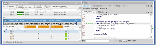
Example – In Figure 5, the old and updated design is shown. Let’s consider the expression exclusion is made at line-23. The expression exclusion for the old design is shown in Figure 6.
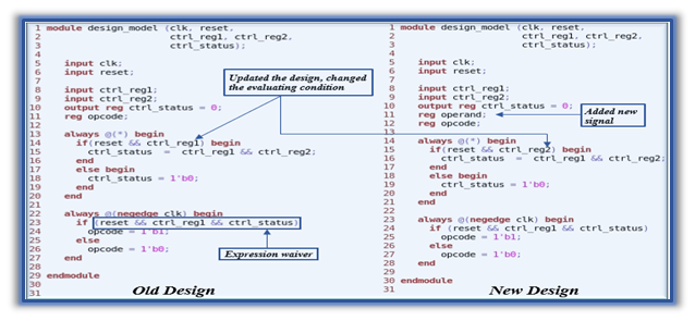
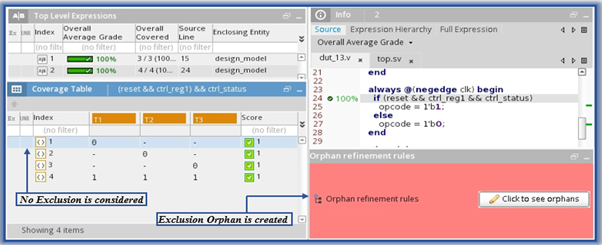
Some modifications are made to the new design. For example, we add the ‘operand’ signal and change the expression condition at line-15. The design is updated but the exclusion file is synchronized with the old design. When this exclusion file is in IMC, expression coverage exclusion made at line-23 (of old design) is not considered and the Orphan rule is created as shown in Figure 7.
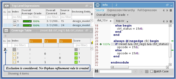
If the set_refinement_resilience command is added in CCF, then, the expression coverage exclusion that is made at line-23 (of the old design) will be automatically accommodated at line 24 (of the new design) as shown in Figure 8. Orphan refinement rules are not created for this expression coverage exclusion.
Note – If there is a design change in the excluded section(s), then those section(s) in IMC are highlighted as Orphans. IMC will also highlight any other exclusions that are not automatically accommodated as per the new design.
So, if the design coverage exclusions are created and later there are design changes, then, the set_refinement_resilience command helps as it avoids manual exclusions.
3. Toggle Scoring for Design signals
In the coverage-driven verification approach, we tend to perform different types of coverage analysis as per the requirements of any project. One of the analysis is the toggle scoring of design module signals. Toggle coverage analysis assures all ports/nets are exercised during verification. As per the project requirements, the toggle coverage can be captured for only module I/O ports, internal signals, or even both. Cadence IMC provides some commands to capture the toggle coverage for module ports and internal signals. The commands are described as below:
- set_toggle_portsonly
- set_toggle_noports
set_toggle_portsonly
Introduction – This command enables the toggle scoring for module ports only. Using this command, the internal signals or nets of the design modules are not scored for toggle coverage throughout the design hierarchy.
Syntax – set_toggle_portsonly
When this command is provided in CCF, the toggle coverage for all the internal signals is not scored even if the entire toggle coverage is enabled for all the modules. This command can be used when checking the connectivity of building blocks since the coverage is captured only for modules ports. If IP verification for all blocks in a chip is done thoroughly with both toggle coverages enabled, then, only the toggle coverage of ports is sufficient at the chip top.
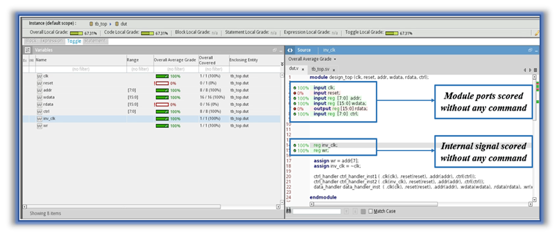
Example – In the design, the modules consist of ports as well as internal signals as shown in Figure 9. Here, in the CCF, no commands are provided and the toggle coverage for both module ports and internal signals are scored as shown in Figure 9.
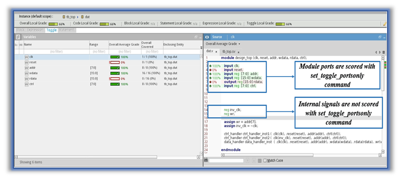
In Figure 10, the set_toggle_portsonly command is provided in CCF and the toggle coverage is scored only for module ports, while the toggle coverage is not scored for internal signals such as inv_clk.
set_toggle_noports
Introduction – This command avoids the toggle scoring of all the module ports, and it scores toggle coverage only for the internal signals. The internal signals scoring is done only once where they are declared. If the same signals are passed on to the other sub-modules in the design hierarchy, then, the toggle coverage for that signal is not captured in the sub-modules. Hence, the toggle coverage for internal signals is scored only at the highest level in the design hierarchy.
Syntax – set_toggle_noports
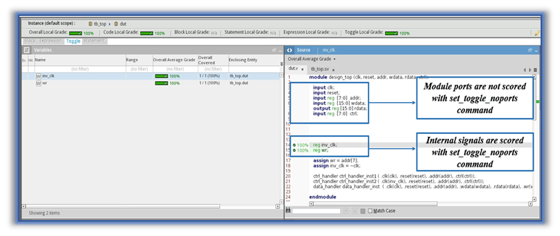
Example – In Figure 11, the set_toggle_noports command is provided in CCF and the toggle coverage is scored only for internal signals, while the toggle coverage is not scored for module ports such as clk and reset.
Note – set_toggle_noports and set_toggle_portsonly are mutually exclusive commands and they can’t be used together in the same CCF else it shouts error.
So, if the toggle coverage analysis is to be done only for modules ports, then, set_toggle_portsonly command is useful. To avoid repetitive toggle scoring throughout the design hierarchy, use the set_toggle_noports command.
Conclusion
In the coverage closure phase, coverage exclusion is time consuming, tedious, and iterative process. If managed smartly, this exercise can be cruised through using the above-mentioned commands. The described commands eliminate manual work by automatically identifying required exclusions from the design hierarchy. Apart from this, Cadence also provides other powerful and resourceful commands that can help in scrutinizing the coverage database more precisely and provide flexibility for coverage data analysis.
As a Verification Alliance Partner for Cadence, eInfochips has expertise in Specman Elite and offers design verification services/consultation for both onsite and offshore in addition to the development of eVC and uVC verification components. These verification components are pre-packaged, reusable pieces of verification code based on industry standards.
To know more about implementing Cadence Coverage commands, please contact our experts today.
Author Details
Dhruvesh
Dhruvesh Bhingradia has completed B.E in Electronics and Communication from Gujarat Technological University. He is working as an ASIC Verification Engineer in eInfochips. He has experience in IP verification for Sensor based chips.
Jaini
Jaini Patel has completed B.E in Electronics and Communication from Gujarat Technological University. She is working as an ASIC Verification Engineer in eInfochips. She has experience in IP verification for Sensor based chips.
Shailesh
Shailesh Kavar works as a Senior ASIC Verification Engineer in eInfochips. He has expertise in SoC ASIC verification chips in sensor and fiber optics chips and has experience on Analog Mix Signaling(AMS) verification.
Bijal
Bijal Simaria works as a Technical Manager at eInfochips. Bijal has worked on SoC verification for various Motion sensing chips, IP, and VIP verification for protocols like USB2.0, USB3.0, MIPI, AHB and many more over the past 16 yrs.
Reference –
[1] Cadence Integrated coverage User Guide – Version 19.09
[2] A Coverage Time-Saving Tip – Functional Verification – Cadence Blogs – Cadence Community
[3] https://community.cadence.com/cadence_technology_forums/f/functional-verification/22453/how-to-create-coverage-configuration-file
[4] https://community.cadence.com/cadence_technology_forums/f/functional-verification/41093/how-to-use-the-set_refinement_resilience-settings-after-design-files-are-updated