Introduction
Exploration is a crucial aspect of autonomous navigation in robotics. Simultaneous Localization and Mapping (SLAM) is a fundamental technique that enables robots to navigate and map unknown environments. Visual Simultaneous Localization and Mapping, or Visual SLAM (VSLAM), is a specific type of SLAM that enables robots to map their surroundings and estimate their own position, i.e., odometry, in real-time using visual input from cameras. This technique has been widely used in various applications, including Mars rovers, Mars helicopters, ground robots, underwater robots, and vacuum cleaning robots. Investigations have been carried out to see how well the Time-of-Flight (ToF) camera works with RTAB-Map for the autonomous navigation of Autonomous Mobile Robots (AMR) using only depth images. The ToF camera captures both infrared (IR) and depth images. The depth image is utilized to create a 3D point cloud. The 3D point cloud and wheel odometry are used by RTAB-Map to output corrected odometry and a 2D occupancy grid map for the autonomous navigation of AMR.
What is the Time of Flight (ToF) Camera?
The ToF camera is an Analog Devices depth camera based on the ADSD3100 TOF Signal Processor. It offers support for data processing on the embedded processor platform in addition to USB, Ethernet, or Wi-Fi connection to a host computer. The ToF camera is designed for use in industrial, automotive, and consumer applications. It uses a time-of-flight method to calculate the distance to objects in the scene, enabling it to create accurate depth maps. The ToF camera provides both Infrared (IR) and depth images and is depicted in Figure 1.
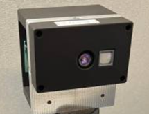
Figure 1: ToF Camera
Architecture of RTAB-Map
Real-Time Appearance-Based Mapping (RTAB-Map) is a graph-based SLAM technique. RTAB-Map incorporates an appearance-based loop closure detector approach and a memory management approach to deal with large-scale and long-term online mapping. The odometry, i.e., the pose of the AMR, is an external input to RTAB-Map. Therefore, any type of odometry that is appropriate for a given application can be used, including wheel odometry, visual odometry, and ICP odometry. Four different input configurations can be utilized with RTAB-Map:
- RGB image, depth image, and odometry
- Stereo images and odometry
- 3D point cloud and odometry
- 2D laser scan and odometry
Figure 2 depicts the different blocks of RTAB-Map. A 3D point cloud and odometry are the inputs that RTAB-Map uses for our use case. Additionally, it needs two input transforms: odom to base_link transform and base_link to camera_link transform. RTAB-Map outputs map to odom transform, 2D occupancy grid map, and corrected odometry. The RTAB-Map node consists of the following blocks: Synchronization, Short-term memory (STM), Long-term memory (LTM), Loop closure and Proximity detection, Graph optimization, and Global map Assembling.
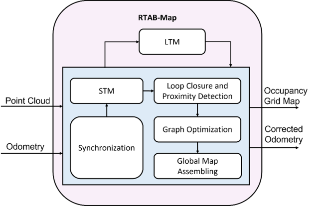
Figure 2: RTAB-Map
Workflow of RTAB-Map and Nav2 stack pipeline with ToF camera
The entire pipeline for performing AMR’s autonomous navigation using rtabmap, ToF camera, and wheel-IMU fused odometry is shown in Figure 3. The wheel-IMU fused odometry is obtained by fusing wheel encoder data and IMU data with the help of an extended Kalman filter to obtain robust odometry. As we can see, there are seven nodes: ToF camera node, image_proc node, point cloud node, rtabmap node, wheel-IMU fused odometry node, Nav2 node, and Rviz node. The next paragraph explains the functionality of these nodes.
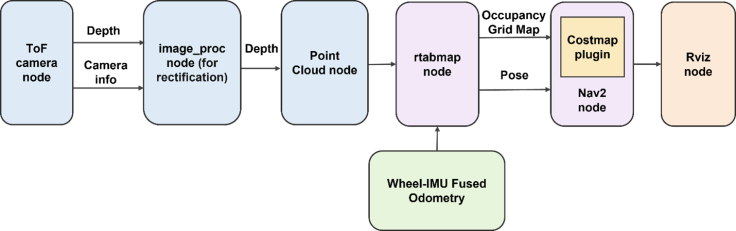
The first node in the pipeline is the ToF camera node, which captures both IR and depth images. The captured images are then rectified by the image_proc node to eliminate tangential and radial distortions. Rectified IR images are used for visualization in Rviz. The point cloud node generates 3D point clouds from rectified depth images. The wheel-IMU fused odometry node estimates the odometry of the AMR using wheel encoders and IMU data. The rtabmap node uses the wheel-IMU fused odometry and generated point cloud to produce the 2D occupancy grid map and corrected odometry (i.e., pose). A Nav2 node uses the generated occupancy grid map and odometry to generate a costmap that is used for path planning and autonomous navigation of the AMR. Finally, the Rviz node is used as a visualization tool to display the IR image, odometry, and occupancy grid map. It also allows for the setting of the goal pose for the AMR. Overall, the pipeline combines various sensors and nodes to enable autonomous navigation of the AMR.
Discussion of Experiment Results
Figure 3 shows the AMR, what it sees through the realsense camera mounted on it, and the resulting 3D point cloud map as a mesh. Figure 4 displays the created map with the given goal state, planned path, and the AMR safely arriving at the goal state by following the planned path.
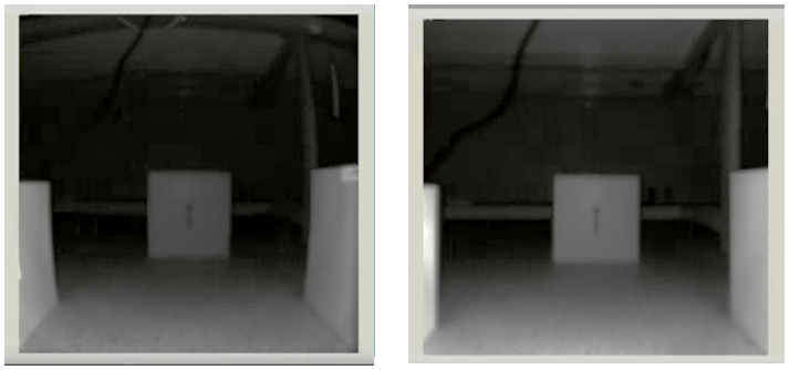
Figure. 4: Left Hand Side Window Shows IR Image Before Rectification And Right-Hand Side Window Shows IR Image After Rectification
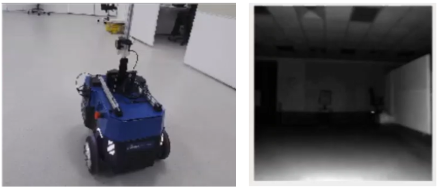
Figure 5: Left Hand Side Window Represents The AMR In The Lab Environment, Right Hand Side Window Shows What AMR Sees Through ToF Camera Rectified IR Image.
Additionally, the point cloud generated using the rectified depth image of ToF camera, shows flat surfaces in real world as curved surface in the point cloud. Hence, post-processing is required to solve this issue. Figure.6 shows occupancy grid map before point cloud filtering and after point cloud filtering. The blue lines in this window denote the estimated odometry of the AMR.
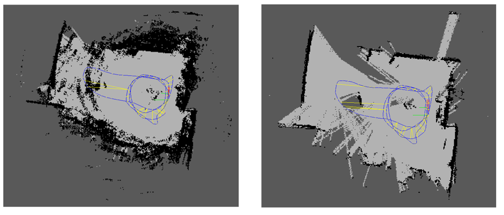
Figure 6 The left-hand side window demonstrates the occupancy grid map before point cloud filtering, while the right-hand side window shows the occupancy grid map after point cloud filtering. The blue lines in both windows denote the estimated odometry of the AMR.
Figure 7 illustrates the various stages of the autonomous navigation process. The first left-hand side figure shows the generated map with the current pose of the AMR. The map is generated by the rtabmap node using the wheel-IMU fused odometry and the point cloud. The second figure in the center depicts the goal position with the planned path. Once the goal position is set in Rviz, the Nav2 node plans a path using the cost map generated from the occupancy grid map and odometry pose. The planned path is displayed in Rviz for visualization. Finally, the third figure on the right-hand side shows that the AMR has reached the goal state. Once the path is planned, the AMR uses the corrected odometry pose and the cost map to navigate towards the goal position. The AMR continuously updates its position using the wheel-IMU fused odometry and occupancy grid map and adjusts its trajectory to follow the planned path. When the AMR reaches the goal position, it stops, and the navigation process is complete.

Conclusion
ToF camera has been integrated into RTAB-Map and Nav2 stack to autonomously navigate the AMR in a lab environment. Various challenges were faced while using ToF with RTAB-Map for autonomous navigation of AMR. The IR and depth images the ToF provided must be rectified because unrectified depth image may lead to inaccurate map. We observed that flat objects were looking curved in the point cloud, and these were resolved through point cloud post-processing. It is necessary to filter the point cloud before giving it to RTAB-Map. In parallel, AMR was building the map and localizing its position in the map for a safe navigation using depth image from ToF and RTAB-Map algorithm. We also saw the successful autonomous navigation of the AMR using ToF camera and RTAB-Map. We suppose that the results from our experiments will accelerate the deployment of ToF for a range of commercial robotics systems.
Authors

Sagar Dhatrak
Sagar Dhatrak completed his M.Sc in electronics science in 2011 and submitted his Ph.D. thesis on monocular visual SLAM in 2021. He’s currently working as a VSLAM specialist at Einfochips (an Arrow company) and working on autonomous navigation of autonomous mobile robots using Visual SLAM. He has worked on embedded systems and robotics related projects for around six years.

Vishal Raval
Vishal Raval has a Bachelor of Engineering (BE) degree in Electronics and Communications. He’s currently working as a Senior Embedded Engineer at Einfochips (an Arrow company). He has around 8 years of expertise in the IT sector. He is a skilled programmer in C, C++, LINUX and ROS2. He is now researching autonomous robot navigation utilizing Visual SLAM with ToF Sensor.