Introduction
Assertion-based verification (ABV) is a powerful verification approach that has been proven to help digital circuits, designers, and verification engineers improve design quality and reduce time to market. But ABV has been rarely applied to analog/mixed-signal verification.
A verification engineer defines assertions from the functional specification of designs. For example, a verification engineer might define assertions to ensure that:
- The design is always in a valid configuration
- The design and the environment communicate correctly
- The design responds correctly to its inputs
This article evaluates why we require mixed signal assertion and shows how languages such as Verilog-AMS, Spectre, and Property Specific Language (PSL) can be used to write complex analog/mixed-signal assertions.
Why do we require mixed signal assertion?
In digital verification, a model is used for assertion-based verification (ABV). This model is based on standard assertion languages, such as PSL and SVA, and system verified in a discrete domain.
However, mixed signal verification system will need to extend the principles of ABV and add some control for a continuous domain. For verifying analog quantity like voltage, current etc., we should use the Verilog-AMS or Spectre/SPICE languages.
There are three types of assertion techniques in mixed signal verification system:
- Verilog-AMS based Assertions
- Spectre simulator based Assertions
- Using Property Specific Language (PSL) with Verilog-AMS
CASE STUDY: UVM-MS Verification Framework for Mixed Signal SoC Download Now
1. Verilog-AMS based Assertions
Assertion, by definition, captures the behavior of a design. In terms of Verilog-AMS, it can be white-box and black box approach of mixed-signal circuits or standalone analog/digital circuits, in that a user can create properties or asserted behavior. Due to this, the user can monitor the design within the hierarchy.
Verilog-AMS language defines a behavioral language for Analog and mixed-signal systems. It consists of complete Verilog and Verilog-A language.
Verilog-AMS designers of the mixed signal system, use modules, which contain high-level behavioral descriptions as well as structural descriptions of the systems and components.
The behavior of each module can be described mathematically in terms of ports and parameters. The structure of each component can be described in terms of the interconnected sub-components. These descriptions can be used in many disciplines such as electrical, mechanical etc. For a continuous system, we mostly use electrical disciplines in the mixed signal system.
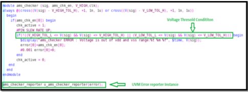
In Figure 1, we check the voltage level of V(sig) signal. This signal will be checked when it crosses some threshold voltage during positive direction (+1), which is mentioned in the sensitivity list.
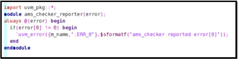
If the voltage threshold condition is not satisfied, an error will be reported through the UVM error reporter.
Figure 2 indicates the UVM error reporter. It generates the error of corresponding assertion/checkers and reports the error of which assertion has failed. It should be instantiated in checker file (As shown in Figure 1)
2. Spectre Simulator based Assertions
The cadence spectre circuit simulator is a modern simulator that simulates the analog and digital circuits at differential equation level.
The spectre assert statement enables to perform checks on design parameters, node voltages, currents, etc., which checks the voltage/current range.
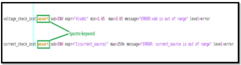
From the above example, in voltage checks, we should define min and max values for voltage range checks. In current checks, we should define only max value. If voltage/current exceed the defined range, it displays the error message and simulation will be terminated if specified level=error.
If level=warning, the simulation will be continued with a warning message.
If multiple assert checks are present, the checklimit statements enable managing which check is enabled/disabled.
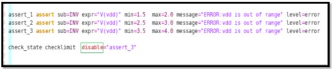
In Figure 4, we have disabled the assert_3 statement using checklimit statement. If we do not use checklimit statement, by default, all assertions are enabled.
RELATED BLOG
3. Using Property Specific Language (PSL) with Verilog-AMS
This section gives a brief of the standard features of PSL and how these features can support mixed signal expressions. The example shown in this section uses a standard PSL and Verilog-AMS language and uses the cadence AMS designer tool.
For the purpose of this discussion, PSL adds the new feature of Verilog-AMS language and supports the cross and above function for clocking event.
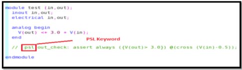
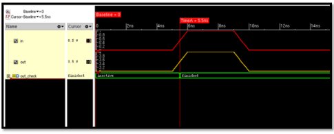
As shown in Figure.5, output voltage V(out) will be checked when input voltage V(in) crosses the 0.5V.
Figure. 6 indicates the assertion status during the threshold condition (input crosses 0.5V).
When we use PSL with Verilog-AMS, the PSL assertions should be commented as shown in Fig.5.
For enabled PSL assertion, we should add the –assert in command line option in the cadence AMS designer tool or in the irun command line as shown in the below example:
irun -assert -f test.fl