Introduction
PERC is an abbreviation of programmable electrical rules checking. It is an important check in the physical verification phase of the design. The reliability of design is checked through various rules and checks with the help of Netlist or GDS. In some checks, a netlist is used as an input while in others a GDS can be used. PERC verifies the different checks for the ESD protection circuits, high current density paths, and high resistance paths, which can damage an IC’s reliability. This paper discusses PERC flow and its significant role in circuit reliability.
There are two modes by which the rules are checked:
1) Netlist mode
2) Layout mode
General Configuration of IC Protection
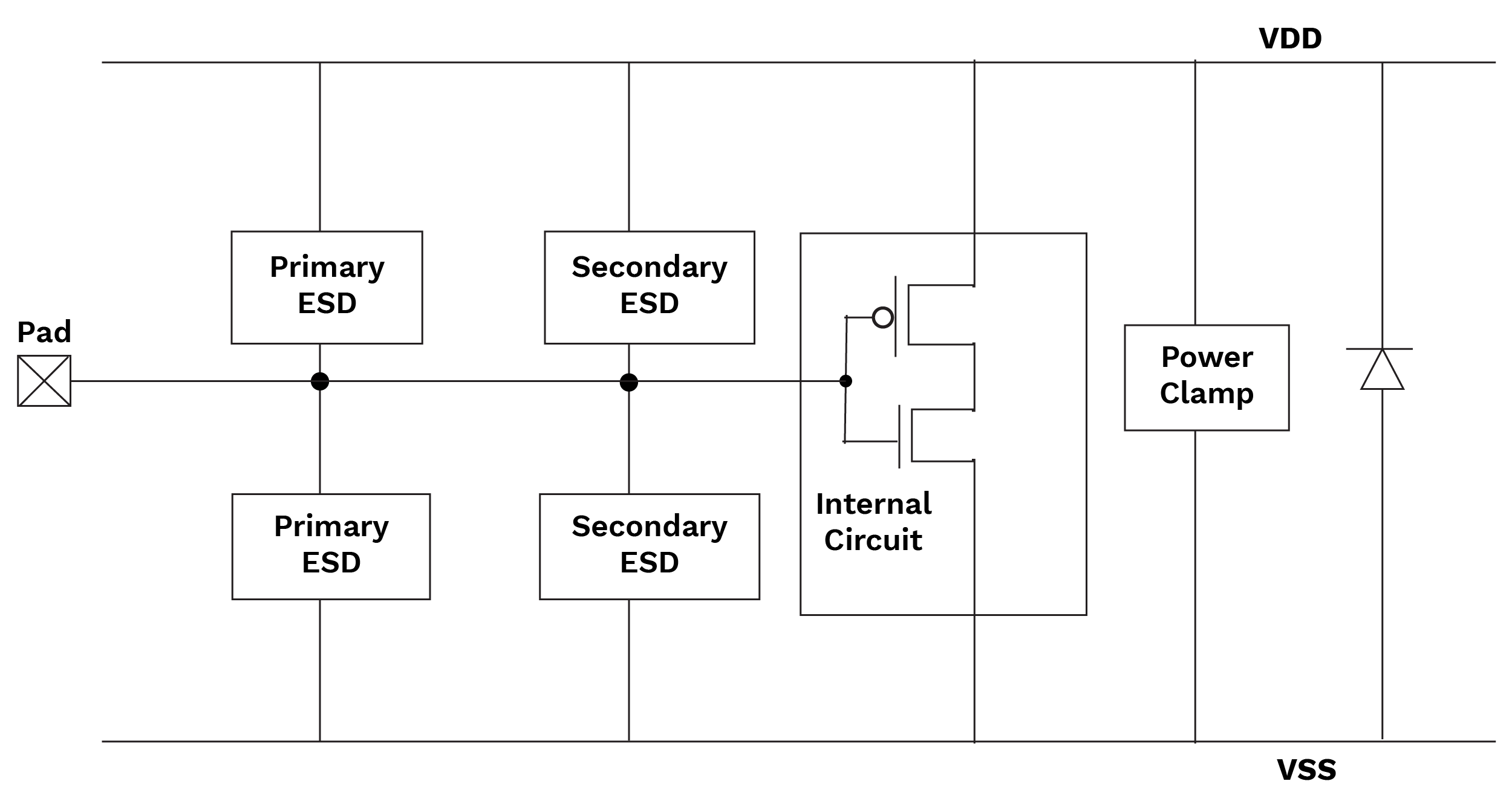
Figure 1 IC protection
Types of PERC checks
- Logic-driven layout
- Topology layout
- Current density
- Point-to-point resistance
Logic-Driven Layout
In the logic-driven layout, the tool checks the layout which is implemented through the connections of the netlist and how it drives the logic of one device to another device in layout and validates the ESD availability in design to provide reliability. Note – The layout should be lvs clean.
It checks the netlist-aware polygons and generates MARK.gds and merges it with input GDS and this provides a merged MARK.gds. With this check, we obtain a marker GDS as output. This is used as an input of current density and a point-2-point check.
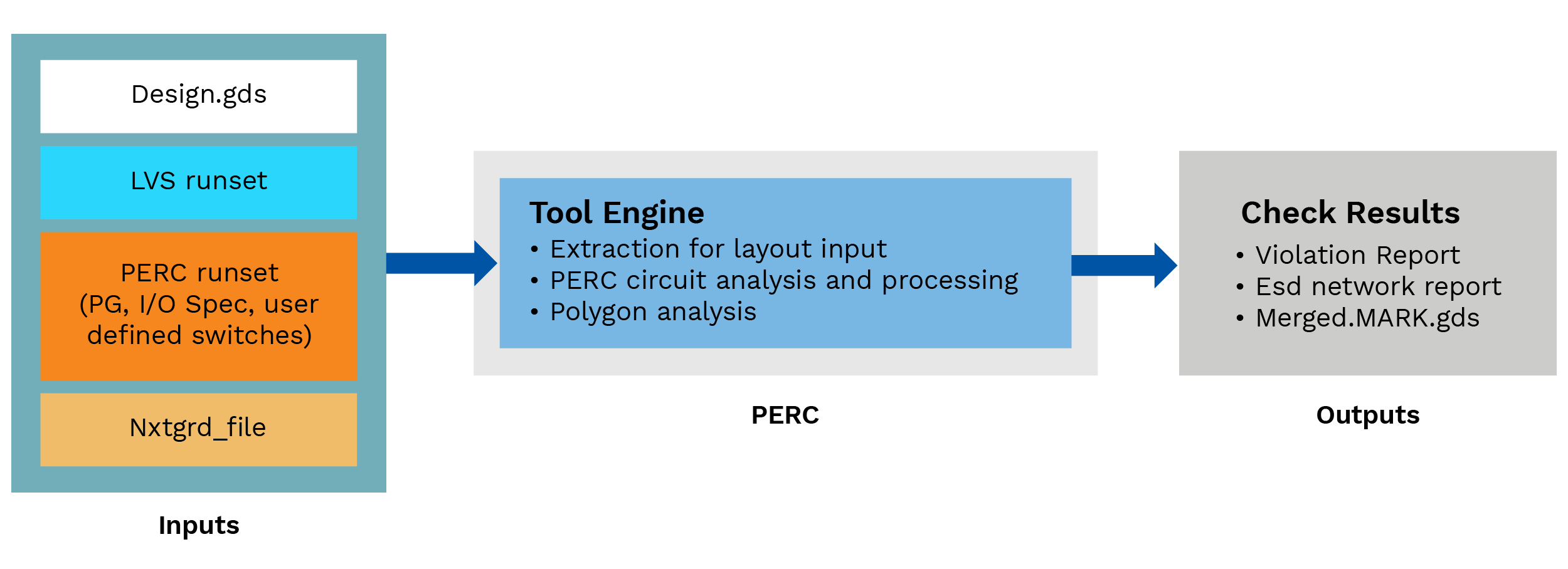
Figure-2 Logic-driven check flow
What Does It Check?
It checks the layout for an identified ESD circuitry, it performs a polygon-based run to check width and area of the layers in the layout for an ESD circuit and after it generates MARK.gds to visualize device at the output. By this check we can ensure that the ESD circuit has proper width and area in the layout as per rule to provide reliability.
Topology Layout
In this check, the tool verifies the topology of the design as pre-determined in the run set. There are various topologies available for ESD protection circuits in the design to provide reliability.

Figure-3 Topology layout checks flow
What Does It Check?
It checks the terminology of devices that are used to protect the circuit from inappropriately high current. As is seen in the figure below, there are various protection devices available, and it checks the terminology of that device from various starting points to end points. For e.g., the starting point should be from pad (A) to VDD (B) and VDD (C) to VSS (D) by diode as per rule.
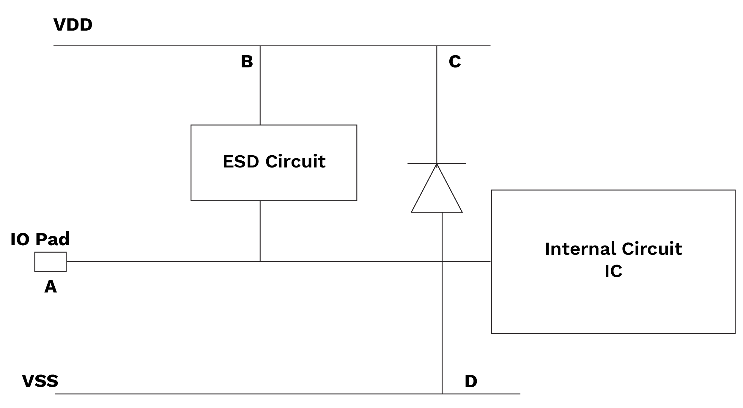
Figure-4 Topology path
Current Density
Current density is an important check that verifies the amount of current passing through each portion of the interconnected paths. It helps the designers locate specific points where a design could fail due to excessive current. The outputs are reports in which one can see the interconnected paths that violate pre-defined current density amount.
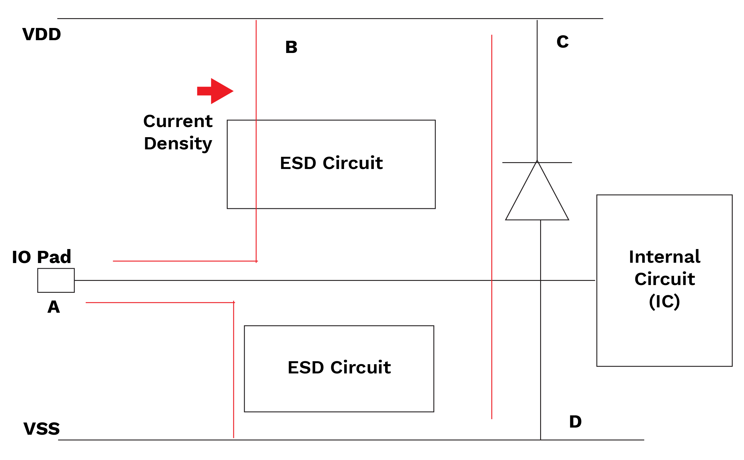
Figure-5 Current density check flow
What Does It Check?
Current density checks play a significant role in PERC. They check the density of current passing through a protection circuit to provide protection against high current density. (E.g., figure-1 current density from pad to ESD devices or pad to power clamp).
As per runset, the current density of all the paths through a protection circuit should be below the predefined value of the runset otherwise it will display an error.
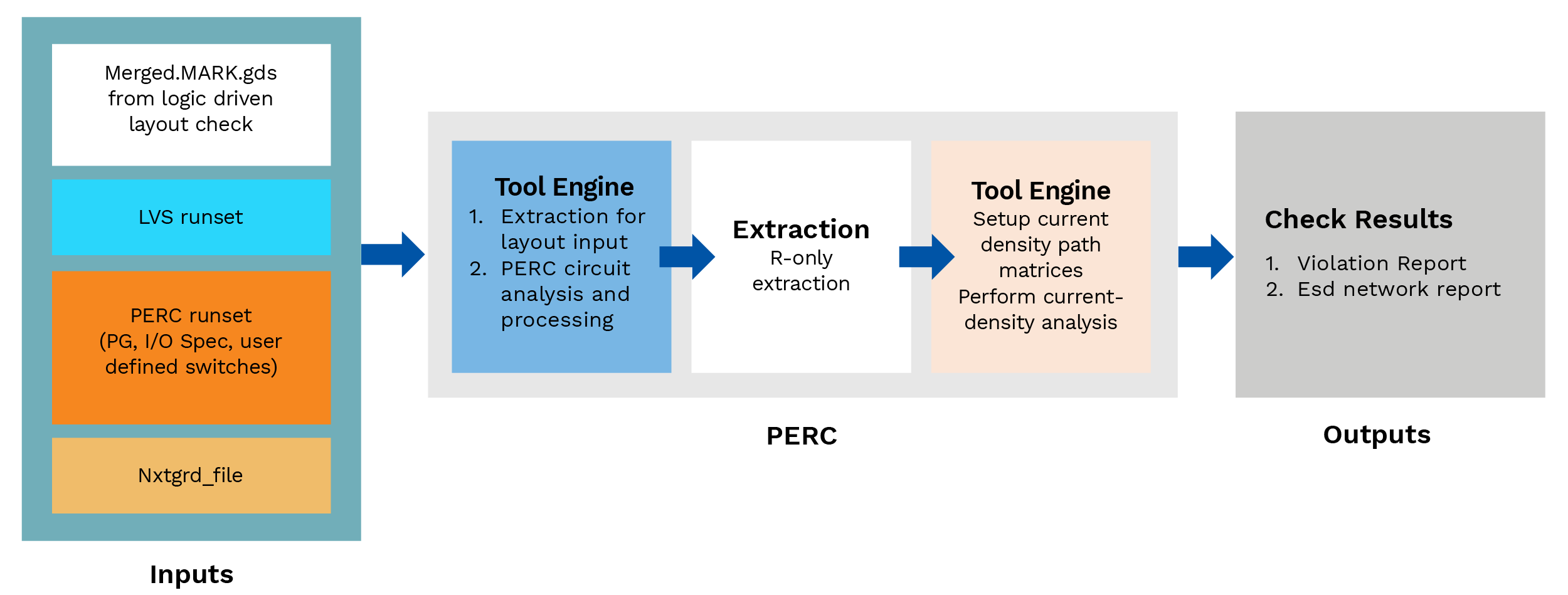
Figure-6 Current density path
Point-to-Point Resistance
This check provides the resistance of a device interconnect level and a report of parasitic resistance of nets that may violate and harm circuit reliability; it also indicates whether the circuitry is as per the rule and will function as designed.
A point-to-point resistance simulation measures the effective resistance of a current path by combining all the individual resistor bodies into total resistance.
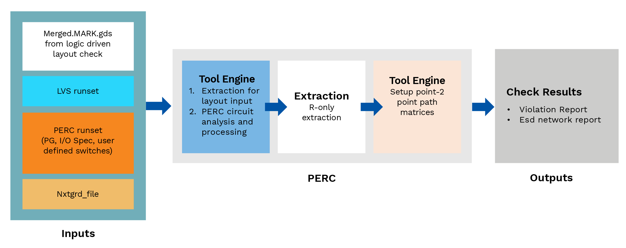
Figure-7 Point-to-point resistance check flow
What Does It Check?
In this check, the tool verifies the resistance of all the paths which are related to ESD protection circuit and are important for reliability. It verifies the resistance of a particular path based on a pre-defined resistance limit through the runset of the check.
If the path is not within the resistance limit, it will display a violation for the path ahead to resolve the over-the-limit path resistance.
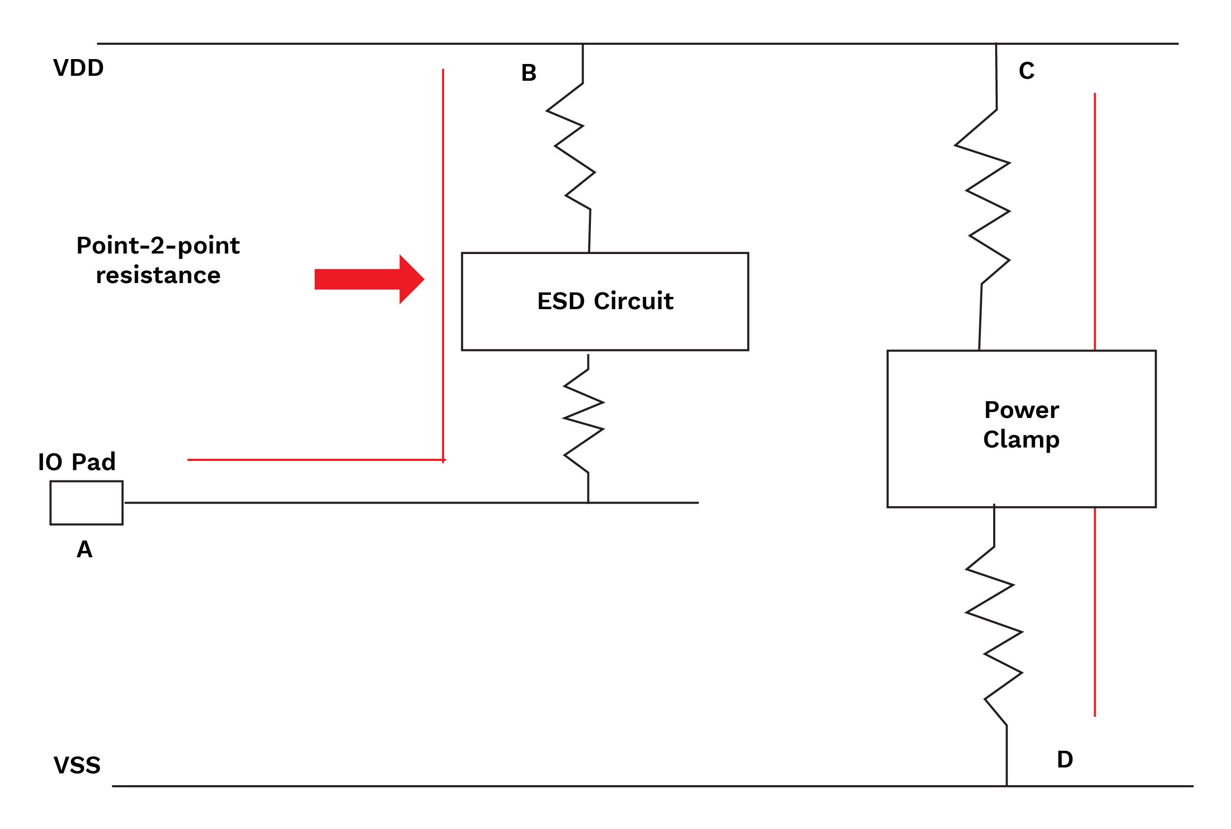
Diagram-8 Point-2-point path resistance.
Rule Coverage
| LDL | TOPO | CD | P2P |
| Checks primary I/O
ESD |
Checks primary I/O
ESD |
Checks primary I/O
ESD |
Checks primary I/O ESD |
| Power clamp | Secondary I/O ESD | Secondary I/O ESD | Secondary IO ESD |
| Latch-up | Power clamp | Power clamp path | I/O-PG to Clamp Path |
| Ground B2B diode | Clamp to Clamp Path | ||
| Ground B2B Diode Path |
PERC Violations
- Topology check
- Violation: ESD.NET.1gU
- Issue: I/O pin is missing the Primary ESD protection.
- Solutions: In the initial phase, to check primary ESD protection, a topology check should be done.
- Point-to-point check
- Violation: ESD.DISTP2P
- Issue: The BUMP to Clamp distance is more, so it is a long path (more resistance) with more than the required resistance as per rule.
- Solutions: To resolve the high resistance path, move the bump closure to clamp to reduce the M14 and M15 resistance to more than required levels.
- Current Density Check
- Violation: ESD.CD.1gU
- Issue: When the ESD current for primary ESD discharge path is more than required as per rule.
- Solution: By increasing the width of layers, it is possible to fix violations on RDL/PG connections.
Conclusion
PERC helps to identify any major reliability issues that can fail the functionality of design, so by PERC flow it is possible to validate that there are no reliability issues in the design with different checks. It helps to reduce delays and failures. PERC is used in ESD reliability, calculation of layer resistance, and diverse types of reports for detailed analysis. It is significantly important for ESD LUP reliability check of designs. It checks the issue of designs which cannot be checked by DRC, EM, or ERC checks.
Know more: Embedded Software Development Services