Predictive analytics and fault diagnostics algorithms entail high-value critical engineering systems to deduce impeding or unknown problems within the underlying system. The benefits of such analytics include abilities to prevent downtime and ensure cost-effective scheduling of maintenance cycles.
A simulation setup can be developed to facilitate algorithm development and testing for fault detection. Fault scenarios can be simulated by injecting fault conditions either into the sensor model or system dynamics at particular time instances. The various faults inserted into the model and respective patterns can be altered to observe and fine-tune the fault-detection algorithms.
This article presents an aircraft jet engine sensor fault diagnostics and prediction implementation using bank of Kalman filters and a Fast Fourier Transform (FFT). The use cases covered demonstrate the model-based development capability to implement such a prognostic system.
Introduction
A gas turbine engine (GTE) is one of the most complex machines ever created, not only due to its constructive intricacies but also for the dynamic behavior and sophisticated engineering required for its operation. Due to its high fuel efficiency, power ratings, and reliability, the GTE is used in various dynamic systems, including airplanes, helicopters, marine ships, and military tanks (the M1 Abrams, for instance). The jet engine mainly works on the reactive forces generated by the exhaust gases emerging from the nozzle. This reaction force called “Thrust” propels the machine forward. Depending on the characteristics of the jet engine — such as the number of spools, the principle of compression, distribution of mass flow, and utilization of exhaust gases in the nozzle — these engines can primarily be classified into four types: turbojet, turbofan, turboprop, and turboshaft. Predictive analysis of faults is performed using a jet engine model with the help of fault analysis algorithms like Fast Fourier Transforms (FFTs) and Kalman filters.
Three state variables can be used to define a jet engine system: pressure, temperature, and density. Thrust is directly proportional to the density: The denser the air, the higher the thrust that can be obtained.
The operation of the jet engine can be broadly described using the Joule-Brayton Cycle. The illustration below depicts the various stages of the Brayton cycle.

jet engine turbine consists of the intake, compressor, combustion chamber, turbine, and nozzle. Atmospheric air enters the engine via the intake, where the air is mainly directed toward the compressor by reducing its velocity and increasing its pressure. No work is done on the air during the intake process. Air enters the compressor with one or more compression stages, where it delivers air at a high pressure and temperature to the combustion chamber. In the combustion chamber, heat addition takes place by the burning of a rich fuel-air mixture. The hot gases enter the turbine and expand. The energy extracted from these hot gases is partly used to power the compressor in the form of kinetic or rotational energy, while the remaining energy is expelled through the nozzle. The nozzle is a convergent tube through which the exhaustive gases are expelled, thereby producing the required thrust.
Mathematical model
Turbofans have a higher propulsion efficiency as compared to the turbojet engine for the same speed range. The image below reflects the station numbering of the mathematical modeling of the turbofan jet engine.

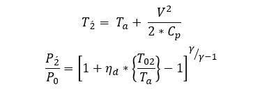
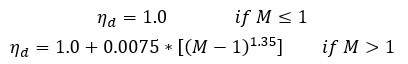
Atmospheric conditions are modeled using an atmospheric block from the Simulink library, which gives ambient temperature, sound speed, ambient pressure, and air density depending on the altitude. The intake/diffuser is used to guide the air into the compressor. An isentropic process is assumed for the intake diffuser system; hence, friction and heat transfer between the air and diffuser is neglected. The diffuser is modeled in a quasi-static state and so the dynamic behavior of the air inside the diffuser is not considered. Stagnation temperature and pressure values of the diffuser exit are calculated as follows:
Pressure recovery is calculated using the U.S. military standards:
The fan is a mechanical component, which is responsible for bringing ambient air to the engine. A major portion of this airflow bypasses the core components of the turbojet engine and is let out by a secondary nozzle. Thus, the net thrust consists of two components: one of cold steam thrust and another of hot steam thrust. Turbofan engines are usually described in terms of bypass ratio, which is defined as the ratio of the flow through the bypass duct (cold stream) to the flow at an entry to the high-pressure compressor (hot stream). The power required to run the fan is supplied through the low-pressure turbine. The performance of the fan is represented using maps, which are 2D lookup tables that provide the mass flow rate values as a function of a normalized fan pressure ratio and speed values.
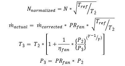
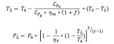
The compressor’s main purpose is to increase the total pressure and temperature of the gas stream required by the engine while absorbing a minimum shaft power. Compressor performance maps are obtained from the actual rig test of the engines. Compressor maps are plotted between the corrected mass flow rate and pressure ratio against corrected speed ratios. With the values of the compressor efficiency and the corrected mass flow rate, the actual mass flow rate and the temperature can be calculated as follows:
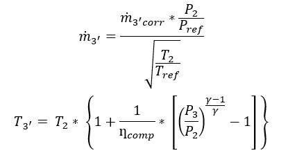
Work done to increase the pressure and temperature of the air can be calculated from the expression:
![]()
High-pressure air from the compressor enters the combustion chamber, where the heat is added by burning of a combustible mixture of vaporized fuel and highly compressed air. A 4% pressure drop is assumed to simulate the dynamics of pressure and temperature in the combustion chamber. The amount of energy imparted to pressurized fuel depends on the fuel air ratio (FAR) and the heating value of fuel being used. The exit temperature of the combustion chamber is obtained using an energy balance equation.

The exhaust gases from combustion expand in the turbine. The basic purpose of the turbine is to drive the compressor. The kinetic energy of the hot gases coming from combustion is converted into mechanical energy, which drives the compressor. The dynamics of the turbine are modeled by using the following equations:
High-pressure turbine:
Low-pressure turbine:
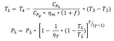 Work done on the turbine by the hot gases coming from the combustion chamber is given by:
![]()
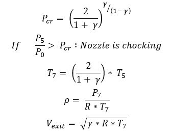
The sole purpose of the nozzle is to convert the potential energy of the gas to kinetic energy to obtain the required amount of thrust. This is accomplished by the geometrical shape of the nozzle. The hot gases from the turbine enter the nozzle at a constant pressure. If the static pressure at the nozzle entry is greater than the ambient pressure, the gases will accelerate to nozzle exit velocity. In order for gases to expand fully, nozzle exit pressure must be equal to ambient pressure. After a certain critical value, even if the ambient pressure drops, nozzle discharge would no longer increase and will remain constant. When the mass flow rate through the nozzle reaches its maximum value, the nozzle is said to be choked. Thus, the mass flow rate of the nozzle depends on two critical factors: the nozzle pressure ratio and the critical pressure ratio. The critical pressure ratio can be defined as the pressure ratio for which the exit nozzle speed is equal to the speed of sound.
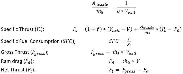
With the help of the above parameters, a specific thrust, specific fuel consumption, and net thrust [4] can be calculated as follows:
In order to determine the steady state condition of the dynamic system, a trim point is calculated. Trimming the jet engine model provides initial conditions and states to drive the engine at a trimmed thrust value for a particular altitude and Mach value.[7]
Remote fault monitoring and detection concept
A fault is considered to be a disallowed discrepancy of any parameter or specific property of the system from the adequate condition, whereas failure is a permanent disruption of a system’s capability to perform its essential function under identified operating conditions.
The recurring event of some faults may damage a system; hence, an early detection of faults is essential in keeping the system running uninterruptedly.
Fault-detection methods are mainly classified into two types: model-based methods and feature-based methods. Model-based methods are based on system modeling and model evaluation. In feature-based methods, mathematical or statistical actions are performed or artificial intelligence (AI) techniques are applied to suitable signal features to extract the information about faults. Feature-based methods are most appropriate for remote monitoring as sensor data provides in situ measurements, which can be transported to the processing center by various means.
To develop a reliable fault-detection mechanism using feature-based methods, there is a requirement for data describing the state of each observed component. Such information is extracted through various sensor signals. The signals usage includes throttle position, rotor speed, temperature, pressure, and supervisory control signals.
Fault diagnostics process flow
There are three major steps as follows:
Access and pre-process data
The sensor data received from the equipment require pre-processing as all of the data are often not quite useful. Pre-processing can be performed using a variety of techniques, such as:
- Time-series data synchronization: To align data, which may contain missing values or data sampled at different rates.
- Advanced signal processing: To eliminate noise from sensor data.
- Feature selection, transformation, and extraction: To determine which data will be helpful for predicting the failures.
Develop fault-detection models
Fault-detection models are based on mathematical, statistical actions, or artificial intelligence algorithms for data clustering, classification, and system identification. These models are typically trained, validated, and tested using predictors and response data.
Deploy models in production
Deployment refers to the application of these algorithm models for prediction using new data. They are deployed on infrastructure such as an enterprise cloud, data mining clusters, and on a real-time embedded platform.
Fault detection in jet engine using bank of Kalman filters and Fast Fourier Transform
The fault-detection problem falls under the sensor values that are used to determine a categorical response: “Fault” or “No-Fault.” There are many classification algorithms available. The following two algorithms are perfectly suited to the purpose of fault detection in a jet engine using sensor data:
- Bank of Kalman filters
- Fast Fourier Transform
Bank of Kalman filters
The Kalman filter is an evaluator that addresses the problem of evaluating the instantaneous state of a linear dynamic system disturbed by white noise. To control a dynamic system, it is important to know the state of the system. The Kalman filter provides means for deducing the missing information from noisy measurements.
A bank of Kalman filter is used for sensor fault detection and isolation (FDI). Each Kalman filter is designed for detecting a specific fault. In this application, we present the Kalman filter based on residual generation. The Kalman filter technique performs a fault detection in two parts:
- Residual generation using a Kalman filter
- Residual calculation
The following figures show plots of faults inserted and faults predicted by a Kalman filter and FFT:
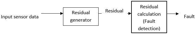
Residual generation and calculation using a Kalman filter


Fast Fourier Transform
Fast Fourier Transform (FFT) is an algorithm used to compute discrete signals, which are derived randomly through data acquisition in terms of:
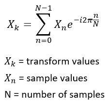
There are N outputs, and the value of Xk is derived from the summation of such outputs. The FFT algorithm is a method to compute the summation of the results in terms of N Log. N comprises four main processes as demonstrated.
In this application, a signature-based fault-detection technique is used. In this technique, signatures are generated using a rotor speed sensor at different points of time. Out of these signatures, some are collected as samples. These samples are used as a reference for real-time input sensor data. At runtime, these reference signatures are used to match with the input rotor speed. Thus, any fault existing in the signal can be easily diagnosed.

Conclusion
In a high-value embedded engineering system, algorithms such FFT, Kalman filters, and extended Kalman filters are a perfect fit because of minimum computation capabilities and modest memory sizes available on edge computing devices. These algorithms further augment intelligence for predictive analytics and fault detection.
References
[1] NPTEL. [Online]. Available: http://nptel.ac.in/downloads/101101002/.
[2] S. Yarlagadda, “Performance analysis of J85 turbojet engine matching thrust with reduced inlet pressure to the compressor,” Toledo, 2010.
[3] N. U. R. a. J. FWhidborne, “A numerical investigation into the effect of engine bleed on performance of single spool turbo jet engine,” Aerospace Engineeering , p. 11, 2008.
[4] C. A. Dominik Klein, “Modelling of a Turbojet Gas Turbine Engine,” p. 7.
[5] R. Royce, The Jet Engine, Great Britain: Renault Printing Co Ltd, 1996.
[6] K. Hunecke, Jet Engines – Fundamentals of theory, design and operation, Osceola: Motorbooks International Publisher and Wholesalers, 2006.
[7] G. F. C. R. a. R. Mayhew, Gas Turbine Theory, London: T. J. Press, Padstow, Cornwall, 1996.
[8] “https://in.mathworks.com/help/simulink/slref/trim.html,” Mat Works. [Online].